background image

Safety information

Product information

Mechanical installation

Electrical installation

Multi axis system design

Technical data

Digitax HD M75X Series Installation and Technical Guide


21

Issue Number: 5                                                         

3.4.1     Drive state representation

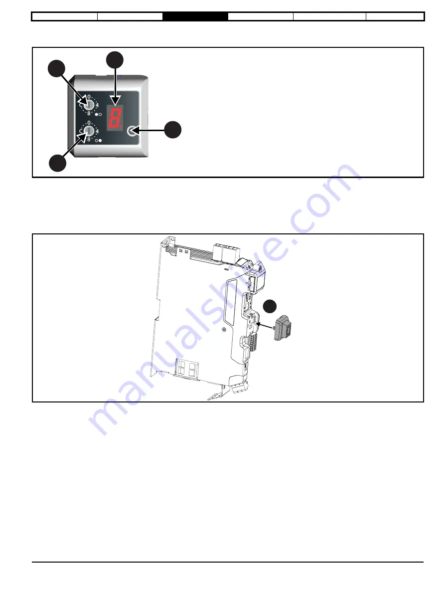
Figure 3-6 KI-Compact display

Refer to the relevant Digitax HD M75X Control User Guide for more information.

3.5      KI-Remote Keypad Adaptor installation

The Digitax HD M75X Remote Keypad Adaptor provides an EIA-485 port for permanent connection to a KI-Remote Keypad or the temporary 
attachment for PC tool connection. The KI-Remote Keypad Adaptor is available from the supplier of the drive. Refer to section 2.8 

Installation and 

system accessories 

on page 14.

Figure 3-7 Installing the KI-Remote Keypad Adaptor without display fitted

1.

 Align the KI-Remote Keypad Adaptor to the display housing and push on until it clicks into place.

1

2

3

4

1

. Single Character display.

2

. Reset switch.

3

. Rotary dial for node address setting (least significant).

4

. Rotary dial for node address setting (Most significant).

1

Summary of Contents for Digitax HD M75 Series

Page 1: ...Installation and Technical Guide Digitax HD M75X Series Variable Speed AC drive for Servo and Induction motors Part Number 0478 0395 05 Issue 5...

Page 2: ...he supplier of an article to inform the recipient if it contains more than a specified proportion of any substance which is considered by the European Chemicals Agency ECHA to be a Substance of Very H...

Page 3: ...losure layout 27 3 9 Rear venting 28 3 10 Enclosure sizing 30 3 11 Enclosure design and drive ambient temperature 32 3 12 Drive cooling fan operation 32 3 13 Braking resistor 32 3 14 External EMC filt...

Page 4: ...is responsible for ensuring that the end product or system complies with all the relevant laws in the country where it is to be used Nidec Control Techniques Ltd The Gro Newtown Powys SY16 3BE UK Mod...

Page 5: ...nt legislation The use of a safety related drive in itself does not ensure the safety of the machine Compliance with safety and EMC regulations depends upon installing and configuring drives correctly...

Page 6: ...e following locations AC and DC supply cables and connections Output cables and connections Many internal parts of the drive and external option units Unless otherwise indicated control terminals are...

Page 7: ...ive While both hardware and software are designed to high standards of quality and robustness they are not intended for use as safety functions i e where a fault or failure would result in a risk of i...

Page 8: ...or multi axis arrangements Connect support for quick start commissioning start up downloadable from controltechniques com Option module connectable Variant description summary Digitax HD M750 M751 and...

Page 9: ...cate the year and the remaining numbers indicate the week of the year in which the drive was built Example A date code of 1710 would correspond to week 10 of year 2017 Model Frame size Drive format In...

Page 10: ...Table 2 1 Maximum RFC S mode ratings In continuous applications the maximum allowed power may override the maximum allowable current Model No of input phases Nominal current Peak current Typical conti...

Page 11: ...control of the motor by applying slip compensation The performance at low speed depends on whether V F mode or open loop vector mode is selected Open loop vector mode The voltage applied to the motor...

Page 12: ...where not already installed 1 2 3 7 5 6 8 9 10 11 12 14 13 15 16 17 18 19 4 12 Number Description 1 Braking terminals 2 AC supply terminals 3 DC bus terminal cover 4 Communication port connections 5...

Page 13: ...a copy of the Quick Start Guide a safety information booklet the Certificate of Quality and supplied accessories including the items shown in Table 2 3 Table 2 3 Parts supplied with the drive Descript...

Page 14: ...fitted Includes DC busbar ground screws 24 V link and communications link 9500 1048 Multi axis kit with SI Option Mounting kit fitted Includes DC busbar ground screws 24 V link and communications link...

Page 15: ...CANopen CANopen option CANopen adapter for communications with the drive Beige SI Ethernet External Ethernet module that supports EtherNet IP Modbus TCP IP and RTMoE The module can be used to provide...

Page 16: ...ssemblies to be at least class V 2 The location and size of the bottom shall cover the area shown in Figure 3 1 Any part of the side which is within the area traced out by the 5 angle is also consider...

Page 17: ...eded then the use of an external EMC filter may be required at the drive inputs which must be located close to the drives Space must be made available for the filters and allowance made for carefully...

Page 18: ...1a Insert a flat head terminal screwdriver underneath the option module slot covers and prise both out in the direction shown as highlighted 1b 2 Install the interface cards into the option module sl...

Page 19: ...ber 5 Figure 3 4 SI Option module installation 1 Remove the protective interface card cover 2 Align and insert the option module tab into the slot on the drive plastic 3 Once the option module tab is...

Page 20: ...act Display can be installed removed while the drive is powered A delay of 10 seconds should be maintained following power up or following a node address dial adjustment before the KI Compact Display...

Page 21: ...pad Adaptor provides an EIA 485 port for permanent connection to a KI Remote Keypad or the temporary attachment for PC tool connection The KI Remote Keypad Adaptor is available from the supplier of th...

Page 22: ...ll the display away from the front cover The tether keeps the display associated to the drive and should not be removed A small terminal screwdriver maybe required to unclip the display A slot in the...

Page 23: ...mensions Cut out only required for rear venting refer to section 3 9 Rear venting on page 28 Enclosure The drive is intended to be mounted in an enclosure which prevents access except by trained and a...

Page 24: ...lation and Technical Guide Issue Number 5 Figure 3 10 Frame 2 dimensions Cut outs only required for rear venting refer to section 3 9 Rear venting on page 28 40 mm 1 58 in 174 mm 6 85 in 12 mm 0 47 in...

Page 25: ...refer to section 3 9 Rear venting on page 28 Mounting screws For single axis drives stand alone two M5 screws are required in the top mounting position and one in the lower mounting position For mult...

Page 26: ...2 Drive width with option module support installed Allow for up to 0 5 mm tolerance with each drive 3 7 Ingress protection label The ingress protection label shown in Figure 3 13 below must remain in...

Page 27: ...e 0 mm Drive Size Spacing between EMC filter and drive A Spacing between enclosure side wall and drive B All 0 mm 0 00 in 10 mm 0 39 in 100 mm 4 in Enclosure 100mm 4in Optional braking resistor and ov...

Page 28: ...enclosure size Allow vertical stacking of drives Reduce the need for a secondary enclosure fan Figure 3 15 Rear vent duct frame 2 illustrated The Frame 1 rear vent kit is supplied with one duct the f...

Page 29: ...Installation of rear vent kit frame 1 shown 1 Attach the rear vent top cover to the top of the drive 2 Align the rear duct tube with the exhaust port ensure the retaining clips on the tube are vertic...

Page 30: ...l EMC filter that is to be installed in the enclosure 3 If the braking resistor is to be mounted inside the enclosure add the average power figures from for each braking resistor that is to be install...

Page 31: ...erally be used with a sheet steel enclosure exact values can be obtained by the supplier of the material If in any doubt allow for a greater margin in the temperature rise Figure 3 18 Enclosure having...

Page 32: ...drive ambient temperature Drive derating is required for operation in high ambient temperatures Totally enclosing the drive in either a sealed cabinet no airflow or in a well ventilated cabinet makes...

Page 33: ...esigned such that it will fail safely under any fault conditions The in built software overload protection is set up at default to protect the resistor Table 3 2 Digitax HD M75X series compact braking...

Page 34: ...to the mounting bracket One M4 nut with washer 1 is provided to use for the ground connection The brake resistor is equipped with a thermal switch the thermal switch should be integrated in the contro...

Page 35: ...Technical Guide 35 Issue Number 5 Figure 3 21 Mounting bracket dimensions Figure 3 22 Brake resistor dimensions 118 mm 4 65 in 15 5 mm 0 61 in 4 5 mm 0 18 in x 2 holes 1 5 mm 0 06 in 30 5 mm 1 20 in 8...

Page 36: ...al Guide Issue Number 5 3 14 External EMC filter 3 14 1 Optional external EMC filter dimensions Figure 3 23 External EMC filter dimensions 4200 3503 Table 3 3 External EMC filter dimensions 4200 3503...

Page 37: ...x HD M75X Series Installation and Technical Guide 37 Issue Number 5 Figure 3 24 External EMC filter dimensions 4200 5033 Table 3 4 External EMC filter dimensions 4200 5033 W C H A D Y V B Part number...

Page 38: ...itax HD M75X Series Installation and Technical Guide Issue Number 5 Figure 3 25 External EMC filter dimensions 4200 6034 Table 3 5 External EMC filter dimensions 4200 6034 Y W C B A H D V Part number...

Page 39: ...Figure 3 26 External EMC filter dimensions 4200 6001 and 4200 6002 Table 3 6 External EMC filter dimensions 4200 6001 and 4200 6002 Figure 3 27 External EMC filter dimensions D H B A C W Torque setti...

Page 40: ...1 97 in M6 5 4 mm 4200 5833 240 mm 9 45 in 255 mm 10 04 in 30 mm 1 18 in 85 mm 3 35 in 290 mm 11 42 in 50 mm 1 97 in M5 5 4 mm 4200 5534 220 mm 8 66 in 235 mm 9 25 in 60 mm 2 36 in 90 mm 3 54 in 298 m...

Page 41: ...mm2 AWG 8 1 5 to 1 8 N m 13 3 to 15 9 lb in M5 2 2 N m 19 5 lb in 4200 3233 16 mm2 AWG 6 1 5 to 1 8 N m 13 3 to 15 9 lb in M6 4 N m 35 4 lb in 4200 5833 16 mm2 AWG 6 1 5 to 1 8 N m 13 3 to 15 9 lb in...

Page 42: ...within specifications Table 3 13 Recommended routine maintenance Environment Recommended action Maintenance Ambient temperature Ensure enclosure temperature remains at or below maximum specified Annu...

Page 43: ...the two tabs inwards to release the fan from the drive frame 2 Partly withdraw the fan assembly and prise out the two way fan plug from the connector This should not be performed by pulling on the fa...

Page 44: ...assembly 1 To ensure the fan is correctly orientated the airflow direction markings on the fan must be positioned as shown in Figure 3 29 2 Position the fan supply cable so that it sits in the recess...

Page 45: ...emoval of frame size 3 cooling fan 1 Using a flat bladed tool press the two tabs inwards to release the fan from the drive frame 2 Partly withdraw the fan assembly and prise out the two way fan plug f...

Page 46: ...igure 3 31 Re fitting frame 3 cooling fan assembly 1 For correct orientation position the fans with the adhesive label and supply cables as shown in Figure 3 31 2 Use a flat blade tool to fully re eng...

Page 47: ...before work may continue Normally the capacitors are discharged by an internal resistor Under certain unusual fault conditions it is possible that the capacitors may fail to discharge or be prevented...

Page 48: ...ation and Technical Guide Issue Number 5 4 1 Power and ground connections Figure 4 1 Digitax HD M75X power and ground connections L3 N L2 L1 Input connections Mains supply L1 L2 Optional line reactor...

Page 49: ...te of the drive Connections are located at the top and bottom of the drive See Figure 4 2 for details Figure 4 2 Supply and motor ground connections NOTE Input phase conductor size Minimum ground cond...

Page 50: ...uence equivalent to 5 voltage imbalance between phases Severe disturbances may be caused by the following factors for example Power factor correction equipment connected close to the drive Large DC dr...

Page 51: ...e DC terminal cover frame 1 2 and 3 1 DC terminal cover Contact the supplier of the drive before connecting a Digitax HD M75X series drive to a DC bus supplied from a regenerative drive or AFE module...

Page 52: ...rew should be tightened to a torque of 1 N m 8 9 lb in 4 3 2 DC busbar cable connection Cable connections to the DC terminals should be made with a suitably insulated M4 ring crimp up to maximum 6 mm2...

Page 53: ...of the external 24 Vdc supply allow for an additional 1 A for 300 ms Figure 4 6 Location of external 24 Vdc supply terminals The 24 Vdc supply connector has been designed to allow wiring from either t...

Page 54: ...cable installation method B2 multicore cable in conduit Cable size may be reduced if a different installation method is used or if the ambient temperature is lower The recommended cable sizes above a...

Page 55: ...electronic short circuit protection which limits the fault current to typically no more than five times the rated output current and interrupts the current in approximately 20 s No additional short c...

Page 56: ...system there is no need for any special precautions In case of doubt the motor supplier should be consulted Special precautions are recommended under the following conditions but only if the motor cab...

Page 57: ...ltage of the drive increases Under default conditions the drive brakes the motor under PI control which extends the deceleration time as necessary in order to prevent the DC bus voltage from rising ab...

Page 58: ...settings Failure to observe the following information may damage the resistor The drive software contains an overload protection function for a braking resistor this function is enabled at default to...

Page 59: ...saving Braking capability will then be reduced which could cause the drive to trip during braking if the value chosen is too large The following external brake resistors are available from the supplie...

Page 60: ...esistor has reached its maximum temperature the drive will disable the braking IGBT and another resistor on another drive will take up the braking energy Once Pr 10 039 has fallen below 95 the drive w...

Page 61: ...4 10 7 Compliance with generic emission standards Requirements for meeting the generic emission standards for the industrial environment IEC 61000 6 4 EN 61000 6 4 2007 A1 2011 The recommendations of...

Page 62: ...Attaching the cable screen bracket to the motor feedback and control wiring frame sizes 1 and 2 Expose outer cable shields 1 The cable screen bracket 2 must be tie wrapped to the motor feedback and c...

Page 63: ...cable screen bracket frame sizes 1 and 2 Slide the tab on the cable screen bracket 1 into the slot formed in the metal side plate 2 and secure to the drive with M4 screw 3 Torque 2 N m 17 7 lb in Fig...

Page 64: ...ti axis system design Technical data 64 Digitax HD M75X Series Installation and Technical Guide Issue Number 5 Figure 4 12 Installation of cable screen bracket frame size 3 Secure the cable screen bra...

Page 65: ...ents of EN 61800 3 2004 A1 2012 to be met for the second environment For longer motor cables the filter continues to provide a useful reduction in emission level and when used with any length of shiel...

Page 66: ...s Installation and Technical Guide Issue Number 5 Figure 4 14 Disconnection of the internal EMC filter on Frame 2 To electrically disconnect the internal EMC filter remove the screw 1 as shown above F...

Page 67: ...t showing ground connections External controller 0V If the control circuit 0V is to be grounded this should be done at the system controller only to avoid injecting noise currents into the 0V circuit...

Page 68: ...ure 4 17 Drive cable clearances Any signal cables which are carried inside the motor cable i e motor thermistor motor brake will pick up large pulse currents via the cable capacitance The shield of th...

Page 69: ...ilter is not required follow the guidelines given in section 4 10 4 General requirements for EMC Ground earth connections on page 67 Refer to section 4 10 EMC Electromagnetic compatibility on page 61...

Page 70: ...the area immediately surrounding the power module Ensure good EMC grounding Figure 4 20 Grounding the drive motor cable shield and filter 1 Ensure direct metal contact at drive mounting points any pa...

Page 71: ...e shielded and the shield s clamped to the drive using the cable screen bracket as shown in Figure 4 20 Remove the outer insulating cover of the cable to ensure the shield s make direct contact with t...

Page 72: ...unding arrangements which permit high transient voltages between nominally grounded points This is a particular risk where the circuits extend outside the protection of a building As a general rule if...

Page 73: ...galvanic isolation of the signal circuit from the motor frame in which case no precautions are required For data networks follow the specific recommendations for the particular network 4 11 Control te...

Page 74: ...Operating in Voltage mode Full scale voltage range 10 V 2 Maximum offset 10 mV Absolute maximum voltage range 36 V relative to 0V Absolute maximum differential input voltage 36 V Working common mode v...

Page 75: ...perating as an output Nominal output current 1 A 1 3 A max Voltage range 0V to 24 V Sample Update period 2 ms output will only change at the update rate of the source parameter 5 10 15 1 6 11 Drive en...

Page 76: ...en the P2 position interface will not be available Depending on the device type used on the P1 position interface the encoder simulation output may not be able support a marker pulse output e g SC EnD...

Page 77: ...edback interface Pr 03 038 Connections 1 2 3 4 5 6 7 8 9 10 11 12 13 14 15 AB 0 A A B B Z Z V 0V Th FD 1 F F D D Z Z FR 2 F F R R Z Z AB Servo 3 A A B B Z Z U U V V W W FD Servo 4 F F D D Z Z U U V V...

Page 78: ...D Z Z FR 3 F F R R Z Z EnDat 4 SSI 5 BiSS 6 DATA DATA CLK CLK Freeze2 Freeze2 None 0 AB Asim Asim Bsim Bsim Zsim Zsim FD Fsim Fsim Dsim Dsim Zsim Zsim FR Fsim Fsim Rsim Rsim Zsim Zsim SSI DATAsim DAT...

Page 79: ...rms sinusoidal signal Operating Frequency 6 8 kHz Input voltage 0 6 Vrms Minimum impedance 85 Common to All Absolute maximum applied voltage relative to 0V 9 V to 14 V Maximum differential voltage bet...

Page 80: ...Servo 3 FD Servo 4 FR Servo 5 SC Servo 12 Type EIA 485 differential receivers Maximum input frequency 512 kHz Line loading 1 unit load Line termination components 120 switchable Working common mode ra...

Page 81: ...terminal descriptions 11 W Clock Not used Not used 12 W Clock Not used Not used AB Servo 3 FD Servo 4 FR Servo 5 SC Servo 12 Type EIA 485 differential receivers Maximum input frequency 512 kHz Line l...

Page 82: ...PDS SR will not provide energy to the motor which can generate torque or force in the case of a linear motor This safety function corresponds to an uncontrolled stop in accordance with stop category 0...

Page 83: ...enient method no special EMC precautions are required Note on response time of Safe Torque Off and use with safety controllers with self testing outputs Safe Torque Off has been designed to have a res...

Page 84: ...ents of each axis The power profile of the whole system including all axis should be used to determine which DC paralleling configuration is the most suitable 5 1 1 DC bus paralleling configuration Co...

Page 85: ...may be reduced depending on the maximum frame block capacitance that a Digitax HD M75X rectifier can support Maximum continuous input power Each Digitax HD M75X series drive has an internal rectifier...

Page 86: ...plication than a single frame block will allow then multiple separate frame blocks each with an individual Digitax HD M75X rectifier can be created Input cable and fusing No supplemental DC fuses are...

Page 87: ...nal and enclosure design enables the DC bus of a number of drives to be connected together using pre made busbars Suitable busbar links for DC paralleling are included in multi axis kits available fro...

Page 88: ...is kits Figure 5 3 DC supply connections and cable routing Larger external DC supply cables for multi axis installations 6 mm2 to 16 mm2 can be accommodated using an external DC bus cable connection k...

Page 89: ...e wrench torque 4 N m 35 4 lb in Figure 5 6 External DC bus cable connection kit Installation step 3 Slide the DC bus cable connection cover into position 1 and secure the DC terminal cover Where a si...

Page 90: ...The 24 Vdc busbar link 1 is a push fit connection which should be inserted adjacent to the 24 Vdc supply connector 2 The 24 Vdc supply connector can be fitted to either outermost drive If the drive i...

Page 91: ...ipple on the DC bus Care should be taken when reducing the threshold however to avoid going below the maximum value of the peak rectified supply voltage as the braking resistor could take power from t...

Page 92: ...ble between drives to minimize space requirement and allow for easy connectivity 5 7 1 Multiple drive mounting Figure 5 9 Multiple drive mounting Allow for up to 0 5 mm mechanical tolerance for each d...

Page 93: ...eet the following designation Top hat rail EN 50022 35x7 5 Figure 5 10 DIN rail alignment Fit the drive over the DIN rail with the bottom rail flush against the lower edge of the recess at the rear of...

Page 94: ...de mounting is permissible with no space required between drives Figure 5 11 Drive mounting dimensions with DIN rail alignment no option module support Cut outs only required for rear venting refer to...

Page 95: ...attachment each drive should be secured with one M5 screw in the top mounting position only 5 8 Example design of a multi axis system A four axis system operates with the power profiles and layout de...

Page 96: ...2210 F see Table 5 1 Multi axis AC input ratings on page 86 The M753 03400160 can therefore be used as the AC source with all drives connected as one frame block via a parallel DC bus As the AC input...

Page 97: ...A 0 2 x 9 62 6 x 9 6 0 5 Input current A 39 67 Suitable external EMC filter refer to Table 6 37 Optional external EMC filter details on page 113 4200 3233 46 A Multi axis kits As both the M753 0240010...

Page 98: ...2 A 1 on the curve the peak current 12 6 A is available for 0 25 s If the peak current of 12 6 A is required for 4 seconds the maximum normalised r m s current is 0 5 x 4 2 2 1 A If the peak current...

Page 99: ...uous output current Open loop peak current RFC A peak current Nominal power at 230 V Motor power at 230 V A A A kW hp 01200022 2 2 3 3 6 6 0 37 0 5 01200040 4 0 6 0 12 0 0 75 1 0 01200065 6 5 9 8 19 5...

Page 100: ...ency on some drive ratings The maximum overload level which can be attained is independent of the speed Drives are rated up to 55 C 131 F 55 C 131 F ratings are available from the supplier of the driv...

Page 101: ...0120 2 2 3 0 12 0 11 9 11 4 03200160 4 0 5 0 16 0 16 0 15 4 400 V 01400015 0 37 0 75 1 5 1 5 1 5 01400030 0 75 1 5 3 0 3 0 2 9 01400042 1 5 2 0 4 1 4 0 3 8 3 6 3 4 3 4 2 9 02400060 2 2 3 0 6 0 6 0 6 0...

Page 102: ...5 1 5 1 5 1 5 1 5 1 5 1 5 1 5 01400030 3 0 3 0 3 0 3 0 3 0 2 9 2 5 01400042 3 5 3 4 3 4 3 3 3 2 2 9 2 5 02400060 6 0 6 0 6 0 6 0 6 0 6 0 5 4 02400080 8 0 8 0 8 0 8 0 7 5 6 5 5 4 02400105 9 1 9 0 8 9 8...

Page 103: ...3200160 16 0 15 8 15 2 13 8 12 6 11 6 10 4 400 V 01400015 1 5 1 5 1 5 1 5 1 5 1 5 1 5 01400030 3 0 3 0 2 9 2 7 2 5 2 3 1 8 01400042 3 2 3 1 2 9 2 7 2 5 2 3 1 8 02400060 6 0 6 0 6 0 6 0 6 0 5 5 4 8 024...

Page 104: ...4 0 4 0 4 0 4 0 4 0 01200065 6 4 6 2 6 1 5 9 5 5 5 0 4 6 02200090 9 0 9 0 9 0 9 0 9 0 9 0 9 0 02200120 11 5 11 3 11 0 10 7 10 3 9 8 9 5 03200160 16 0 16 0 16 0 16 0 16 0 14 6 13 6 400 V 01400015 1 5 1...

Page 105: ...The DC bus capacitors have a storage period of 10 years 6 1 10 Altitude Altitude range 0 to 3 000 m 9 900 ft subject to the following conditions 1 000 m to 3 000 m 3 300 ft to 9 900 ft above sea leve...

Page 106: ...absolute accuracy is further limited by the absolute accuracy of the analog input The following data applies to the drive only it does not include the performance of the source of the control signals...

Page 107: ...100 kA Fuses The AC supply to the drive must be installed with suitable protection against overload and short circuits Table 6 19 shows the recommended fuse ratings Failure to observe this requiremen...

Page 108: ...1 0 75 16 02200120 1 0 75 16 03200160 1 1 5 14 01200022 3 0 75 20 01200040 3 0 75 18 01200065 3 0 75 16 02200090 3 1 0 14 02200120 3 1 5 12 03200160 3 2 5 12 01400015 3 0 75 20 01400030 3 0 75 20 0140...

Page 109: ...7 lb in Ground busbar 2 0 N m 17 7 lb in Internal EMC filter screw 0 8 N m 7 1 lb in Compact brake resistor mounting screw 0 8 N m 7 1 lb in Compact brake resistor thermistor screw 0 3 N m 2 7 lb in P...

Page 110: ...orque Off STO tested to 20 V m 80 1000 MHz 6 V m 1 4 2 0 GHz 3 V m 2 0 2 7 GHz Module enclosure Level 3 industrial IEC 61000 4 4 Fast transient burst 5 50 ns 2 kV transient at 5 kHz 100 kHz repetition...

Page 111: ...61800 3 2004 A1 2012 The 2004 revision of the standard uses different terminology to align the requirements of the standard better with the EC EMC Directive Switching frequency EMC filter Frame 3 3 m...

Page 112: ...t also includes establishments directly connected without intermediate transformers to a low voltage power supply network which supplies buildings used for residential purposes The second environment...

Page 113: ...kg lb mA mA 4200 3503 1 30 27 3 250 250 6 1 20 0 7 1 5 5 4 10 8 4200 5033 1 55 50 1 250 250 9 9 20 1 2 2 6 11 22 4200 6034 1 65 7 60 250 250 5 5 20 1 8 4 0 3 4 6 8 4200 8744 3 7 7 7 480 480 3 8 20 0...

Page 114: ...rounding bracket 62 63 64 H Hazardous areas 17 I Internal EMC filter 63 Isolator switch 72 M Mechanical Installation 16 Motor cable interruptions 71 Motor isolator disconnector switch 72 Motor operati...

Page 115: ......

Page 116: ...0478 0395 05...

Reviews: