8
5.2) Connect bluebus devices
BlueBUS is a technology that enables the connection of compatible
devices with just two wires conveying the electric power and com-
munication signals. All devices are connected in parallel on the same
2 BlueBUS wires, without the need to observe polarity; each devices
is recognised individually as it is assigned with an exclusive address
during installation. BlueBUS can be used, for example, to connect
the following: photocells, safety devices, control pushbuttons, indi-
cator lamps, etc. The SOON control unit recognises each one of the
devices connected by means of a specific self-learning phase and is
able to detect all possible faults in maximum safety and with the
utmost precision. For this reason each time a device is connected to
or removed from BlueBUS the self-learning phase must be repeat-
ed, as described in paragraph “7.1 - Memorising devices”.
5.2.2) Photosensor ft210b
Photosensor FT210B combines in a single device a force limitation
system (type C to the standard EN12453) and a presence detector
that detects obstacles on the optic axis between the transmitter TX
and receiver RX (type D to standard EN12453). On photosensor
FT210B the signals of the sensitive edge status are sent via the pho-
tocell beam, integrating the 2 systems in a single device. The trans-
mitting section on the mobile leaf is battery-powered, thus eliminat-
ing unsightly connection system; special circuits reduce battery con-
sumption to guarantee a lifetime of up to 15 years (see details of the
estimated lifetime in the product instructions).
A single FT210B device combined with a sensitive edge (e.g. TCB65)
enables the safety level of the “main edge” as required by the standard
EN12453 for any “type of use” and “type of activation”. Photosensor
FT210B combined with “resistive” sensitive edges (8,2Kohm), is safe
with single faults (class 3 to standard EN 954-1). It is equipped with a
special anti-collision circuit to prevent interference with other detec-
tors, even not synchronised, and enables the addition of other photo-
cells; for example in the case of transit of heavy vehicles where a sec-
ond photocell is normally positioned at 1 m from the ground.
For further information on connection methods and address assign-
ment, see the instruction manual for FT210B.
5.3) Connect devices to stop input
STOP is the input that causes immediate shutdown of the move-
ment followed by a brief inversion of the manoeuvre This input can
be connected to devices with an output for NO normally open con-
tact, NC normally closed contact, constant resistance 8,2K
!
or opti-
cal devices, such as sensitive edges.
As in the case of BlueBUS, the control unit recognises the type of
device connected to the STOP input during the self-learning phase
(see paragraph “7.1 - Memorising devices”); after which a STOP
command is activated whenever a variation with respect to the
learned status is detected.
When set accordingly, more than one device can be connected to
the STOP input, also different from one another:
• Several NO devices can be connected in parallel with no limit to
number.
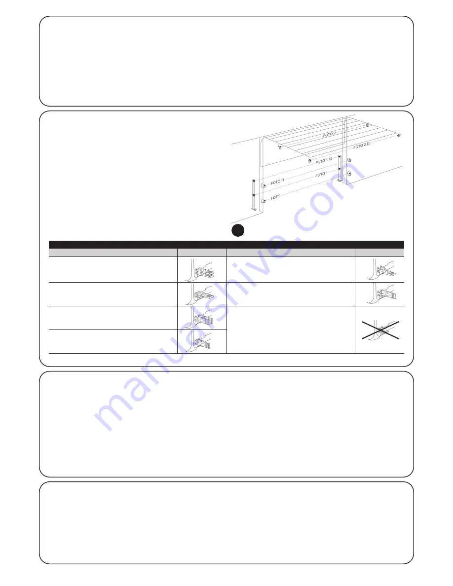
5.2.1) Photocells
The “BlueBUS” system enables, by means of address assignment
using the specific jumpers, recognition of the photocells by the con-
trol unit and assignment of the correct detection function. The ad-
dress assignment procedure is performed both on the TX and RX
(setting the jumpers in the same way) and ensuring that there are no
other pairs of photocells with the same address.
On an automation for sectional doors with a SOON gearmotor, pho-
tocells can be installed as shown in Fig. 8. After installation the self-
learning phase must be repeated on the control unit, as described in
paragraph “7.1 - Memorising devices”.
8
PHOTO
Photocell h = 50
With activation on closing
PHOTO II
Photocell h = 100
With activation on closing
PHOTO 1
Photocell h = 50
With activation on closing and opening
PHOTO 1 II
Photocell h = 100
With activation on closing and opening
PHOTO 2
Photocell
With activation on opening
PHOTO 2 II
Photocell
With activation on opening
PHOTO 3
CONFIGURATION NOT ADMITTED
Table 2: photocell addresses
Photocell
Jumpers
Photocell
Jumpers


