


INSTALLATION AND MAINTENANCE INSTRUCTIONS
VPA 200/70
General
VPA 200/70 is a water heater primarily intended for con-
nection to heat pumps. It is also suitable for use with other
heat sources.
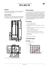
Assembly
Unscrew the water heater from the wooden pallet. Screw
the supplied plastic feet into the stand. The water heater
can be raised by screwing out the length of the feet.
261
35
8
237
610
4b
2
6
1520
20
70
481
74
357
520
240
600
77
360
523
60
St‰
llbar
15
ñ 40
1
10
7
5
170
261
35
8
237
610
4
3
2
6
1520
20
70
481
74
357
520
240
600
77
360
523
60
S
‰
‰
dett
‰
v‰
15
ñ 40
1
7
5
170
4a
DESSA ÄR FEL OCH GAMLA
237
615
357
520
20
70
74
240
600
77
360
523
170
35
1520
Ställbar
20 - 55
261
481
55
530*
4b
1
4a
5
2
6
10
8
7
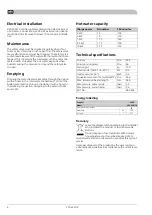
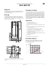
* Distance to hole for entry of cable to submerged tube
(8).
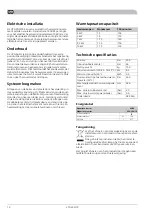
Pipe installation
The water heater is only designed for upright installation.
Internal support bushes should be fitted when a plastic
pipe or annealed copper pipe is used. The water heater
must be fitted with the requisite valves, such as a safety
valve, shut-off valve, non-return valve, and vacuum valve.
An overflow pipe must be routed from the safety valve to
a suitable drain. The size of the overflow pipe must be the
same as on the safety valve. Route the overflow pipe from
the safety valve enclosed along its entire length and ensure
that it is frost proof. The outlet of the overflow pipe should
be visible.
Equipment
Cold water inlet, Ø 28 mm
1.
Hot water outlet, Ø 28 mm
2.
Docking connection, supply pipe (from heat pump*), Ø
28 mm.
4a.
Docking connection, return pipe to heat pump*/radiator
return, Ø 28 mm.
4b.
Supply pipe to radiators, Ø 28 mm
5.
Venting, double-jacketed container.
6.
Immersion heater connection, G 50 int. Plugged on deliv-
ery.
7.
Sensor pipe (int. Ø 8 mm, length 85 mm), hot water
heating control
8.
Adjustable feet
10
*or another external heat source
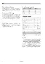
Pressure drop diagram
Primary side
Connection (4a) and (4b).
0
0
mvp
kPa
500 1000 1200
0
l/h
2000
0,2
0,4
0,8
2
8
4
2500
6
0,6
Pressure drop
Flow
5
VPA 200/70
GB