


2-10
|
ni.com
Chapter 2
Installation and Configuration
Remote Voltage Monitoring and Control
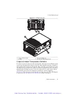
The NI PXIe-1082 chassis supports remote voltage monitoring and inhibiting through a female
9-pin D-SUB (DB-9) connector located on the rear panel. Table 2-1 shows the pinout of
the 9-pin D-SUB (DB-9) connector.
Caution
When connecting digital voltmeter probes to the rear 9-pin D-SUB
(DB-9) connector, be careful not to short the probe leads together. Doing so could
damage the power supply.
You can use a digital voltmeter to ensure all voltage levels in the NI PXIe-1082 chassis are
within the allowable limits. Referring to Table 2-2, connect one lead of the voltmeter to a supply
pin on the remote voltage monitoring connector (9-pin D-SUB) on the rear panel. Refer to
Table 2-1 for a pinout diagram of the remote voltage monitoring connector. Connect the
reference lead of the voltmeter to one of the ground pins. Compare each voltage reading to the
values listed in Table 2-2.
Note
Use the rear-panel 9-pin D-SUB connector to check voltages only. Do not use
the connector to supply power to external devices.
Table 2-1.
Remote Inhibit and Voltage Monitoring Connector Pinout
DB-9 Pin
Signal
1
Logic Ground
2
+5 VDC
3
Reserved
4
+3.3 VDC
5
Inhibit (Active Low)
6
+12 VDC
7
Reserved
8
-12 VDC
9
Logic Ground
1
2
3
4
5
6
9
7
8
Artisan Technology Group - Quality Instrumentation ... Guaranteed | (888) 88-SOURCE | www.artisantg.com


