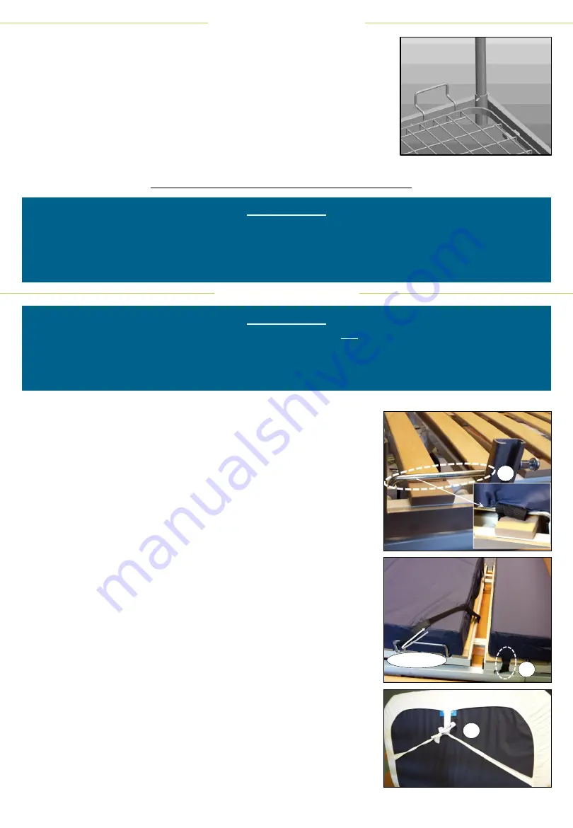
FITTING THE LIFTING POLE
5
The lifting pole can be fitted into the sockets on either the left- or
right-hand-side of the mattress support, at the head end. Rotate the
pole until the locator-pin slots securely into the corresponding
groove in the socket. This prevents the pole from rotating and holds
it centrally above the user, ensuring it is securely positioned for use.
Hang the grab handle over the end of the pole between the two
vertical pins and adjust the strap to the required length.
When not in use, the lifting pole can be lifted slightly to free the locator-pin, allowing it to be
rotated out of the way. It must NOT bear any weight when in this position.
PLEASE NOTE:
•
The lifting pole has a safe working load
of 75 kg, and is not designed to support the user’s full
bodyweight. It is also not suitable for therapeutic purposes.
•
Please check the grab handle and strap for wear or damage regularly, and replace any worn or
damaged parts immediately.
FITTING THE MATTRESS
To fit the mattress:
1. On each side of the mattress, near the centre, there is a black
fabric retaining loop. The loops are used to hold the mattress in
position when the bed profiles or transitions to the chair
position. The loops should be hooked over the metal anchor
bars on the mattress support directly beneath them.
2. Two Velcro straps are attached to the foot end of the mattress
support; the straps are used to hold the end of the mattress in
position during use. The straps should be positioned at 45
degrees over the top of the corners of the mattress, passed
through the triangular section of the mattress retaining bars on
the mattress support, folded back and secured with the Velcro.
3. The straps should be tensioned to the point where the
mattress is firmly secured in place but avoiding puckering the
mattress or the cover.
4. Next the small foot block should be installed, looping the small
Velcro straps on the underside of the block around the
mattress support beneath.
5. When the fitted sheet with sewn-in pillow case set is used, the
outer edge of the covers for the mattress and the foot block
are elasticated around the edge to hold them in place. Two tie
straps
–
one across the middle and one at the head end of the
sheet
–
give added security. The head-end tie strap should be
passed through the loop at the top edge of the sheet, before
being tied across the back of the mattress with a bow.
PLEASE NOTE:
•
The Mattress should be fitted with the mattress platform flat (i.e. not profiled/in chair position).
•
The Rota-Pro® graphic screen-printed on the mattress cover should face upwards and the
rounded corners should be positioned at the head end of the bed. This is a non-turn mattress
and as such will only fit correctly one way round.
1
2 & 3
4
5
Summary of Contents for Rota-pro CB3RP-210-90
Page 11: ......


