Nexus 21 Transcend Pro Installation Instructions Manual Download Page 6


Types of Controls for Nexus 21 Systems 


All Nexus 21 Systems come standard with a 

wireless remote control

 and receiver. We offer a choice of two different types of remotes: 

IR and RF (both of which are explained in detail below). Our standard control type is RF, so unless you specifically requested the IR 
version when you made your purchase, you probably received the RF controls with this Mount System. The method of installation for 
each type of remote control is slightly different, so you should now identify which type of remote you have by reading below, and 
then follow the instructions for that type of remote. 
 

NOTE:


If you will be using the Mount with a home control system (like the ones made by companies such as Crestron or Control 4) 

the most common form of control is to WIRE IT DIRECTLY to the relays of your home control system. This direct-wire method is called 

Integration by Contact Closure

, and is accomplished by using the Contact Closure Hardware that is supplied with the IR Control Kit to 

connect the Mount to your home control system.  


Before You Begin the Installation: Identify Your Control Type 


IR (Infrared)


 This control option allows you to utilize a 3

rd

 party universal style remote control to raise and lower the Mount.  

Your universal remote will “learn” the IR codes from the provided IR Handset, which will enable you to control the 

mount.  The 

universal remote will then communicate with the 

“eye” located on the IR Receiver via your 3

rd

 party emitter (or flasher). Instructions 

for setting the 

Mount’s

 travel limit are on Page 19.


   NOTE:  

If you are NOT planning on using a 3

rd

 party Universal Remote, switch to the RF setup.  (There is no charge for swapping)   


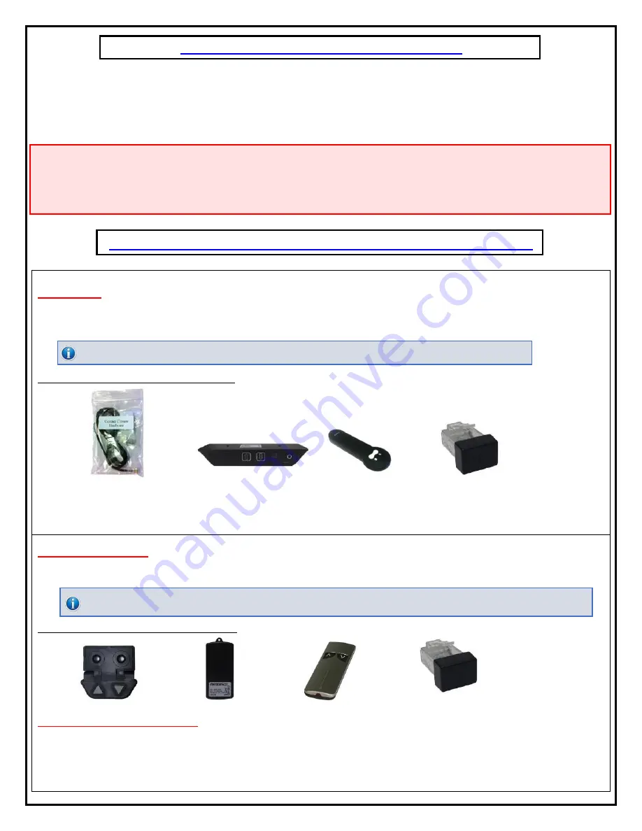
These are the parts included with IR controls:   


Contact Closure Hardware                  IR Receiver 

              IR Handset              Height Limit Insert 


RF (Radio Frequency)


This system utilizes a wireless remote control handset that sends a radio signal to the RF Receiver. The 

radio signal can go through cabinet walls and does not require line-of-sight. Instructions for setting the Mount System travel limit are 
on Page 19.


TIP:

 Planning to integrate the Mount 

with your UNIVERSAL REMOTE CONTROL? The RF version of the Nexus 21 controls won’t do it. Switch to IR.


These are the parts included with RF controls:


               Backup Switch                 RF Receiver 

            RF Handset 

           Height Limit Insert 

Integration by Contact Closure


 To direct-wire the Mount controls to a home control system (Crestron, Control 4, AMX, etc.) 

you will use the Contact Closure Hardware. You wo

n’t use any Nexus 21 receiver or handset for this type of control because you will 

use the handset or control pad that comes with your home control system.  

Instructions for setting up the System using Contact 

Closure are on “

Page 22

”.


Summary of Contents for Transcend Pro

Page 1: ...Transcend Pro Installation Instructions...

Page 2: ...1...

Page 3: ...efer to the dimensional diagram shown on Supplemental Page A at the end of this document Before beginning assembly and installation please make sure that you have all items included on the list If any...

Page 4: ...Use to connect the RF Receiver to the Control Box Ends have RJ 45 connectors One foot long Hardware 1 Four 4 3 8 x 3 Lag Screws w Washers 2 Four 4 10 x 0 25 Phillips Screws 3 Four 4 Zip Ties 4 Two 2 A...

Page 5: ...ystem is affixed can support four times the weight of the system 9 Risk of electric shock Do not attempt to open the Control Box 10 To reduce risk of fire or electric shock do not expose parts to rain...

Page 6: ...niversal remote will learn the IR codes from the provided IR Handset which will enable you to control the mount The universal remote will then communicate with the eye located on the IR Receiver via y...

Page 7: ...the Mount 2 Assembling the Mount 3 Installing the Mount 4 Attaching the TV to the Mount 5 TV Level Adjustment 6 How to Set the Tilt 7 How to Set a Lower Limit 8 Cable Management Information 9 Mainten...

Page 8: ...nt Control Box 2 Motor Cables Power Cord Wired Backup Switch CSI Control Kit or RF Control Kit Step 2 Connect the Motor Cables to Ports 1 2 which are located on the front and back face of the Control...

Page 9: ...th Actuators This will initialize them so they start and stop at the same point UP DOWN Step 4 Connect the Power Cable to Port AC on the Control Box and connect the other end to a Wall Outlet Step 3 I...

Page 10: ...s Screws Swivel Pivot Nut Swivel Pivot Bolt Step 7 Attach the Screen Back Plate to the Mount using the Swivel Pivot Bolt Swivel Pivot Nut and 2 Washers using the diagram shown to the right Ensure the...

Page 11: ...p 11 Place the Enclosure into the top slot of the Transcend Pro and Fasten it to the recess box using 4 Phillips Screws Step 10 Place the Control Box with all of its connections into the Control Box e...

Page 12: ...s the Up button to run the mount to the top most position then disconnect it from power Step 12 Remove the Cable Management Covers on the interior sides of the Recess Box Step 13 Place all the cables...

Page 13: ...ot have a Shelf or Mantel proceed to the next step Step 17a Using shelf depth D locate the cell in Table 1 to determine the H Minimum Clearance Step 17b Using the shelf depth D locate the cell in Tabl...

Page 14: ...nor adjustment for the position of the mount if needed Step 18 Place the top end of the Transcend Pro into the cutout in the wall push it up then push the bottom half of the mount into place Note Be s...

Page 15: ...lts to adjust its position If the mount is still unlevel the cutout may need to be expanded Finer adjustments for the level of the TV can be made separately and are covered later in Adjustments sectio...

Page 16: ...dware Pack Step 24 Attach the Vertical Mounting Bars as high as possible on the Back of the TV Note This will ensure the mount has the most possible downward travel and is fully concealed when in the...

Page 17: ...f or mantel below it Step 27 Hang and center the TV on the Screen Back Plate then release the spring loaded Screen Locks to secure the TV in place Step 26 Press the Down button on the Wired Backup Swi...

Page 18: ...tep 2 Loosen or Tighten the Bolt on the Top of either Vertical Mounting Bar to raise of lower that side of the TV Note Maximum adjustment of 0 5 Degrees Step 3 Re engage the Spring Loaded Screen Lock...

Page 19: ...en the Screw from the Screen Back Plate Note There is only 1 degree of Tilt in this position Step 2 Fasten each Screw into the Pem Nuts located on the left and right side of the Screen Back Plate Step...

Page 20: ...eset if it is obstructed To set a Lower Limit follow the steps listed below 1 Press the DOWN button on the Wired Backup Switch or Remote Control 2 Once the Mount reaches your desired position press th...

Page 21: ...r Linkage Arm then zip tied to it Ensure enough slack remains so that the wires can freely move when the mount is operated Once all Cable Management is finished check the full range of motion again to...

Page 22: ...uration of its life Please follow these steps once every 3 months 1 Lubricate all joints every 3 months More lubrication may be required for outdoor installations 2 Visually check all bolts every 3 mo...

Page 23: ...5 Blue is GROUND Pin 8 You will need 2 Normally Open Relays one for UP and one for DOWN Each relay should receive a momentary pulse of 750ms to 1000ms Do not latch a contact closure command as this w...

Page 24: ...23...

Page 25: ...24 866 500 5438...

Reviews: