


16
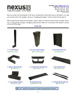
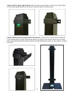
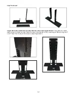
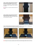
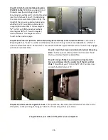
Step 12: Attach the
Upper Rear Support Bracket
to
the rear panel of your cabinet.
Fully extend the
Lift Column
. Using (2
) #10 x ¾” THWS Screws
fasten
the
Upper Rear Support Bracket
to the rear panel of
the cabinet.
Note:
Make sure to center the
Lift Column
from left
to right.
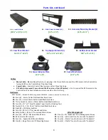
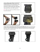
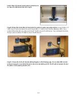
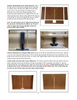
Step 13: Attach the
Lower Rear Support Bracket
to
the rear panel of your cabinet.
Using (4)
#10 x ¾”
THWS Screws
fasten the
Lower Rear Support Bracket
to the rear panel of the cabinet.
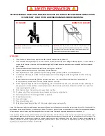
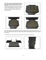
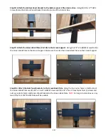
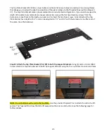
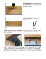
Step 14: Attach both
Base Plate Brackets
to the base of the cabinet.
Using (12
) #10 x ¾” THWS Screws
(6
screws per side) fasten both
Base Plate Brackets
to the base of the cabinet.
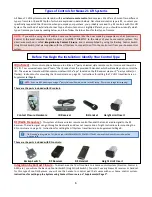
NOTE:
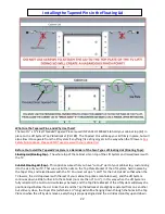
Step 15a - 15c assumes all joints are Butt Joints when determining the dimensions for each Panel.
Summary of Contents for L-45ens
Page 1: ...TV Lift System Model L 45ens Installation Instructions ...
Page 2: ...2 ...
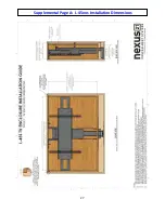
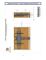
Page 27: ...27 Supplemental Page A L 45ens Installation Dimensions ...
Page 28: ...28 Supplemental Page A L 45ens Installation Dimensions Page 2 ...
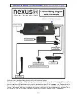
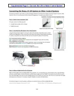
Page 30: ...30 Supplemental Page C Connect the Lift to Home Control System ...
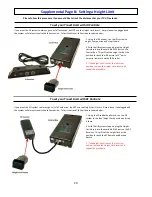
Page 31: ...31 ...
Page 32: ...32 866 500 5438 ...