background image

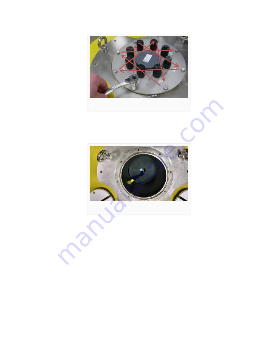
3.  Remove the (8) bolts with lock washers from the buoy plate using a 9/16″ socket wrench.


4.  Lift the buoy plate off of the data well. Disconnect the 6-pin UW-plug running between the solar

regulator and the X2-CB and protect the connectors. This will expose the data well where the
battery and solar regulator are installed.


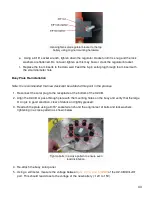
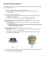
Remove lid to access the buoy data well.

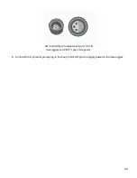
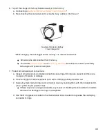
Top view showing UW-6 power cable.

40

Summary of Contents for CB-650

Page 1: ...CB 650 Data Buoy User Guide Last Revision 27 June 2022 Date Generated 1 July 2022 Copyright 2022 NexSens Technology Inc...

Page 2: ...ing UW6 BULK Pinout Wiring Options M650 Beacon for CB Series Data Buoys Installation Operation CB Series Data Buoy Instrument Cage Installation CB CCA Anti Rotation Collar Use of Sacrificial Anodes on...

Page 3: ...t Mooring Deployment 4 Troubleshooting and Maintenance Verify Battery Voltage of a CB Series Buoy Replace a Battery in a CB Series Data Buoy Battery Removal New Battery Installation Test a CB Series B...

Page 4: ...oyancy of 650 lb 295 kg Three 4 passthrough holes with female NPT bottom threads allow for quick connection of instrument deployment pipes and custom sensor mounts Data Well The waterproof compartment...

Page 5: ...users may drill their own holes and install connectors into Solar Tower Three 32W solar panels on the solar tower capture sunlight from any direction and charge batteries located inside the data well...

Page 6: ...e key specifications of the CB 650 buoy are given below Hull Outer Diameter 38 0 96 5cm Hull Height 22 0 55 9cm Data Well Inner Diameter 10 3 26 2cm Data Well Height 21 5 54 6cm Pass Through Hole Diam...

Page 7: ...NexSens does not endorse any particular mooring strategy and systems should be designed and executed based on careful consideration and local knowledge of the deployment site Electrical connections Ma...

Page 8: ...e life jackets gloves steel toed boots etc Proper lifting and mooring techniques Awareness of on site and surrounding weather conditions and advisories Despite careful planning unforeseen situations a...

Page 9: ...topside wet mate sensor connectors for standalone operation or installed in the CB 25 platform 3 X2 CB Buoy Mounted Data Logger waterproof lid mounted package for integration on CB Series data buoys...

Page 10: ...50 only 2 CB A05 x contains one to four 28 A Hr batteries depending on buoy capacity see table below The following table shows what battery harness models each CB Series data buoy model has capacity f...

Page 11: ...solar regulator systems in the data well The bottom of the data well has two welded standoffs for connection of battery mount posts and hardware for securing user supplied batteries including mounting...

Page 12: ...ion of user supplied sensors Instructions for installation and use of these bulkhead connector cables is available here Securing Data Well Plate Any time the data well plate will be resealed first ver...

Page 13: ...oy data wells capped with CB PTL pass through lids or blank lids with user drilled holes It consists of an N style female connector integrated on the bulkhead for external antenna connection and 1m pi...

Page 14: ...a UW 6 power bulkhead connector UW6 BULK port Information regarding the port pinout and different options for wiring power to user supplied electronics is supplied below For installation instructions...

Page 15: ...ocally Molex Wire Solar Regulator Connection Battery Terminal Connection Yellow Solar Black Common GND Negative GND Orange Battery Red Positive V The internal jumper inside the solar panel connector d...

Page 16: ...olor and default 15 flash minute pattern Model M650H Y Installation Note Install the M650 beacon and other top side mounts before installing the solar tower on the buoy 1 Follow the included M650 illu...

Page 17: ...rench Operation The M650 is controlled using an IR programmer that is normally provided with the beacon It also has an on board manual user interface on the bottom that can be used to change settings...

Page 18: ...Turn beacon on and off Check the battery pack charge status Change the flash pattern and intensity The M650 battery can also be user replaced Replace battery 18...

Page 19: ...s standard with the others Model number CAGE L is 44 112 cm in length and has a wider profile It comes standard with CB 650 CB 950 and CB 1250 buoys The cage is a critical component of the ballast wei...

Page 20: ...single bolt connection is sufficient for small buoys in calm waters However a CB CCA Buoy Cage Anti Rotation Collar may be used for added security in rough waters or when suspending sensor strings fr...

Page 21: ...ws connecting the two anode halves Zinc is chosen for the anode material because it is a readily available metal with a lower reduction potential 0 76V than the steel of the buoy frame This offers the...

Page 22: ...on buoys Airmar WX Series Weather Sensors Gill MaxiMet Weather Sensors LI COR Terrestrial Light Sensors Lufft WS Series Weather Sensors METER ATMOS Weather Sensors Vaisala WXT Series Weather Sensors M...

Page 23: ...amp Underwater PAR Sensor Mounting Arm YSI EXO Sonde Mooring Clamps Profiling Instrument Mounts Mounting brackets for commonly used current meters and profiler ADCP instruments Nortek Aquadopp Buoy In...

Page 24: ...es buoys is near the water surface without instruments connected Therefore any top side weight added above the water s surface e g sensors sensor mounts must be appropriately counterbalanced by ballas...

Page 25: ...example suppose a weather sensor is mounted 36 above the water surface Figure 2 In that instance the sensor mount will cause more buoy instability than mounted 24 above the surface Figure 3 As a resul...

Page 26: ...int configurations the mooring hardware does not contribute to the ballast weight If needed add inch galvanized chain 2 3lb ft to the bottom of the cage or utilize NexSens 25lb ballast weight that can...

Page 27: ...standard with either 1 2 galvanized chain CB 25 CB 25 SVS or an installed steel instrument pipe CB 40 for ballast Model Buoyancy lbs Minimum Recommended Ballast Weight lbs 1 CB 25 SVS 25 CB 25 25 CB...

Page 28: ...t handled by adding weight to the bottom of the buoy and not relying on the mooring weight to act as ballast Additionally the weight associated with biofouling growth can impact the buoy buoyancy and...

Page 29: ...deployments can be designed with all chain or a combination of heavy bottom chain and light water column chain Deeper water moorings may need to use a combination of chain and rope Example catenary m...

Page 30: ...ons where the floatation may not be adequate to support the mooring weight Extra floatation can also free motion for wave measurement applications or offer additional resistance to horizontal loading...

Page 31: ...sulting in the buoy listing to one side Damage can result with topside equipment and solar panels becoming submerged Additional surface or subsurface floatation may be required Depiction of horizontal...

Page 32: ...ese moorings are useful for suspending sensor lines by pulling the mooring lines free and clear Rough water shifting bottom or horizontal loads can tangle two point moorings and lead to chafing and ca...

Page 33: ...ats and weights on the mooring lines create an S shape which provides spring action in the water column Waves and water level changes are easily managed This mooring type is most common on deep water...

Page 34: ...e bottom of the buoy frame or instrument cage Refer to the articles below to learn more about CB Series buoy characteristics before deployment Buoy Ballast Weight Stability NexSens CB Series Buoy Ball...

Page 35: ...e tie into the hole on the shackle pin and run it through the shackle loop right image below Pull tightly to secure and trim the excess Deployment Personnel safety is the number one priority when depl...

Page 36: ...the boat begin by connecting all mooring hardware including the mooring line s connection to the bottom eye of the CB series buoy 2 Lift the anchor over the side of the boat and release it in to the w...

Page 37: ...sonnel and equipment Place the connected marker buoy in the water 4 Move to the desired location of the data buoy Pay out the mooring line from the first marker buoy to the data buoy as the boat is mo...

Page 38: ...e voltage between pins 3 V and 4 GND on the SOLAR port Healthy SLA battery voltage is 12 0 14 9V SLA batteries which have fallen below 10V should be replaced while batteries between 10 12V should be c...

Page 39: ...ll obstructions as a clogged vent can cause high pressure combustible gas build up in the well due to outgassing from the batteries DO NOT use power tools to remove the plate Tools Required Electrical...

Page 40: ...buoy plate off of the data well Disconnect the 6 pin UW plug running between the solar regulator and the X2 CB and protect the connectors This will expose the data well where the battery and solar reg...

Page 41: ...a 10mm socket wrench Immediately cover the loose cable end with electrical tape to prevent it from contacting the data well and short circuiting a Repeat this step for the other battery terminal and c...

Page 42: ...e second then third and fourth batteries if applicable attaching the previous battery s ring terminal cable to the corresponding battery terminal above it each time 3 For all Systems a Once the final...

Page 43: ...of the X2 CB 2 Align the X2 CB or pass through plate with the mounting holes on the buoy and verify that the large O ring is in good condition clear of debris and lightly greased 3 Reattach the plate...

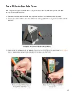
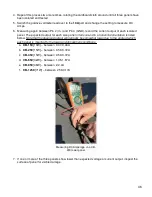
Page 44: ...6 Connect the 6 pin solar panel plug to the buoy s SOLAR port to reapply power to the data logger UW 6 SOLAR port receptacle pinout for X2 CB data loggers and CB PTL pass through lids 44...

Page 45: ...r of debris 2 Use cardboard or cloth to shade two of the three solar panels on the buoy and move the tower into sunlight 3 Record the DC voltage observed between Pins 2 V and 3 GND of the solar tower...

Page 46: ...n and in a horizontal orientation is listed below Note that the observed output will normally be somewhat lower due to the angle at which each panel is mounted to the tower and atmospheric conditions...

Page 47: ...y s SOLAR port as soon as the buoy is removed from service a The solar panel cable plug has an internal jumper that acts as a switch to supply on board electronics with power If the solar panel cable...

Page 48: ...d port connections a Inspect all sensor ports and cable connections ensuring all O rings are present and there are no signs of moisture or damage b Cover all logger or cable receptacle ports with a UW...

Page 49: ...chnology Inc product damage or failure caused by failure to install operate or use the product in accordance with NexSens Technology Inc written instructions abuse or misuse of the product failure to...

Reviews: