background image

B

Verify that the power LEDs on the left and right 

front control panels are illuminated to ensure that 

the controller nodes are receiving power and the 

power modules are functioning properly.

C

Verify that the heartbeat LED 

 is blinking 

yellow in 2-3 second intervals.

D

Verify that the drive carrier LEDs are illuminated in 

green.

E


If all LEDs indicate normal operational status, 

reattach the front bezel to the UNITY

33

00:

a

Hook the left end of the bezel onto the chassis.

b

Fit the right side of the bezel onto the chassis.

c

Turn the key lock at the right end of the bezel 

to the lock position to secure the bezel to the 

chassis.

NOTE: 

Unity Storage Systems are hot pluggable; 

Once in service, powering down is not normally 

required to add a Unity Storage Expansion.

Monitor the Unity Storage 

System

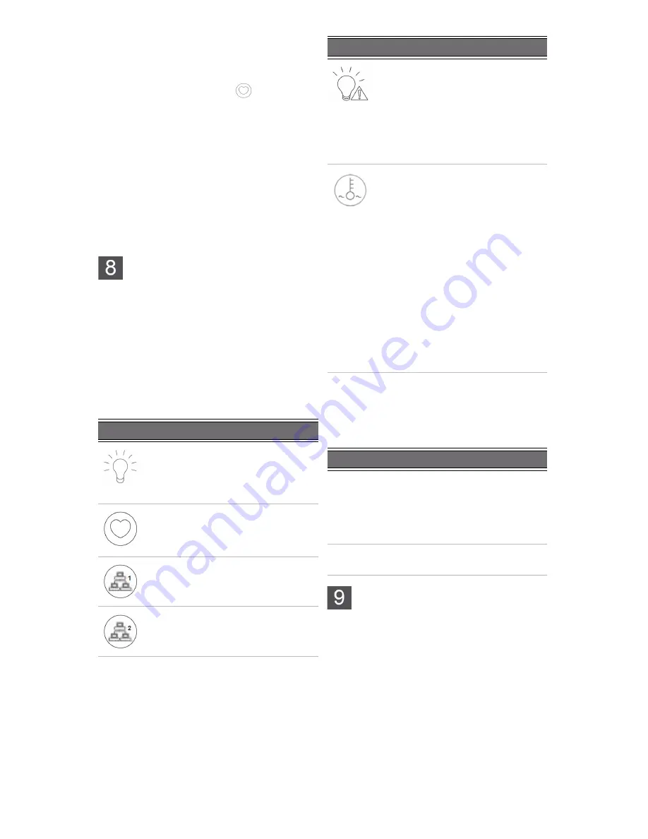
This section describes the front panel LEDs that help 

you monitor the Nexsan Unity Storage System.

Control panel LEDs

The two control panels located on the front left and 

right sides of the Unity system have several LEDs. 

These LEDs provide you with critical information 

related to the corresponding node.
If the Fan fail LED or Power fail LED illuminates, 

replace the component as described in the 

Nexsan 

Unity Storage Expansion Reference Guide

Drive carrier LEDs

Each drive carrier has two LEDs. If a drive fails, 

replace the drive as described in the 

Nexsan Unity 

Storage Expansion Reference Guide

 at 

www.nexsan.com (see Support > Unity > 

Documentation & Online Help).

 Configure the management 

interface (nx99)

Configure network settings for the UNITY

33

00 

management interface (nx99) using the nxadmin 

CLI.

NOTE: 

It is strongly recommended to configure the 

management interface (nx99) on a different subnet 

from the primary data network interface (nx0). 

However, it is acceptable to configure both 

interfaces on the same subnet in a flat network 

environment.

Configure the management interface (nx99) 

using the nxadmin CLI

A


Connect to the UNITY

33

00 via KVM (console). 

See 

Step 3: Connect the KVM dongles

.

B


When connected, enter 

nxadmin

 to log on. 

LED

Indication

Power

Indicates power is being supplied to 

the system’s power supply module. 

This LED is illuminated when the 

system is operating.

Heartbeat

This is a Controller heartbeat LED and 

indicates that power is being supplied 

to the Controller.

NIC1

Indicates network activity on the LAN1 

port when flashing.

NIC2

Indicates network activity on the LAN2 

port when flashing.

Power fail 

Indicates a power supply module has 

failed. The second power supply 

module takes the load and keeps the 

system running, but the failed module 

should be replaced as soon as 

possible. 
This LED should be off when the 

system is operating normally.

Fan fail 

When flashing, this LED indicates a 

fan failure. 

When illuminated continuously, this 

LED indicates an overheated 

condition, which may be caused by 

cables obstructing the airflow in the 

system or the ambient room 

temperature being too high. 

Check the routing of the cables and 

make sure all fans are connected and 

operating normally. You should also 

check to make sure that the chassis 

covers are installed. 

This LED remains flashing or 

illuminated as long as the error 

condition exists.

LED

Indication

Green

z

A steady green LED indicates the

drive is powered on.

z

If this LED is not lit, the drive is not

getting power.

z

If this LED is flashing, the drive is

being accessed (read or write).

Red

z

A steady red LED indicates a drive

failure.

LED

Indication

6 — UNITY3300 and UNITY

 US316

 Quick Start Guide

Summary of Contents for UNITY3300

Page 1: ...th PMBus 2 Fan assembly 4x 80mm and 4x 40mm PWM cooling fans Redundant cooling 3 On board 10GbE LAN ports 2 per node z Right port Primary data network interface nx0 optional z Left port Management Interface nx99 and IPMI interface NOTE If you are using a 1GbE port for the management interface these ports will be used for data with the left port still being used for the IPMI interface 4 KVM connect...

Page 2: ... back for both the left and right rail assemblies z FASTier SSD and HDD drives Check that the components included in your shipment correspond to your packing slip z Two SAS cables HD Mini SAS to HD Mini SAS z Two power cords z Two KVM leads z One electrostatic discharge ESD wrist strap Components Not Included In Your Package z Client computer z Network switches z Network cables Item Name Descripti...

Page 3: ...k B Line up the inner chassis rails with the front of the outer rack rails C Slide the inner chassis rails into the outer rack rails keeping the pressure even on both sides you have to depress the locking tabs when inserting D Push the UNITY3300 completely into the rack you should hear the locking tabs click into position E Tighten the thumbscrews that hold the front of the UNITY3300 to the rack X...

Page 4: ...pond to your packing slip z Two power cords z Two SAS cables HD Mini SAS to Mini SAS Rack the UNITY US316 Follow the same steps as racking the UNITY3300 Storage System see Rack the UNITY3300 on page 3 Connect the UNITY3300 X Step 1 Connect the network cables A For the Unity Management Interface nx99 and IPMI plug an Ethernet cable into the on board LEFT GigE RJ 45 connector B Optional if there is ...

Page 5: ... B Connect a Fibre Channel cable from that same host or switch to one of the Fibre Channel HBA ports 2 on the back of the second UNITY3300 controller Fibre channel connections Power on Unity components X Step 1 Power on the UNITY US316 if applicable A Press and hold the power button located on the right front panel of the chassis until the power LED lights up B Wait approximately 1 minute for the ...

Page 6: ...o configure the management interface nx99 on a different subnet from the primary data network interface nx0 However it is acceptable to configure both interfaces on the same subnet in a flat network environment Configure the management interface nx99 using the nxadmin CLI A Connect to the UNITY3300 via KVM console See Step 3 Connect the KVM dongles B When connected enter nxadmin to log on LED Indi...

Page 7: ... Optionally select a Server Time Zone C Optionally select Unity CallHome settings D Click the Next button to continue X Step 4 Configure network settings A Enter IP addresses for the Primary Data Network Interface nx0 In the examples shown with the exception of the subnet mask the last digit of the network addresses increments from 0 to 10 or 190 to 200 This practice is a useful standard if you ne...

Page 8: ... Storage System statistics Storage Pools File Systems and LUNs X What s next Please see the Unity Setup Guide included with your Unity System for setup instructions for z Authentication z Adding a storage pool file system and LUN z Mounting an iSCSI LUN on a Windows client z Mapping a CIFS file system to a Windows client Safety notices z This equipment must be installed and operated in compliance ...

Reviews: