


Xperience platform
All of Nexmosphere’s controllers are built on the same platform principles. If this is your first time using a Nexmosphere
controller, we recommend to first read
https://nexmosphere.com/technology/xperience-platform/
to learn the basics about
our platform and its terminology.
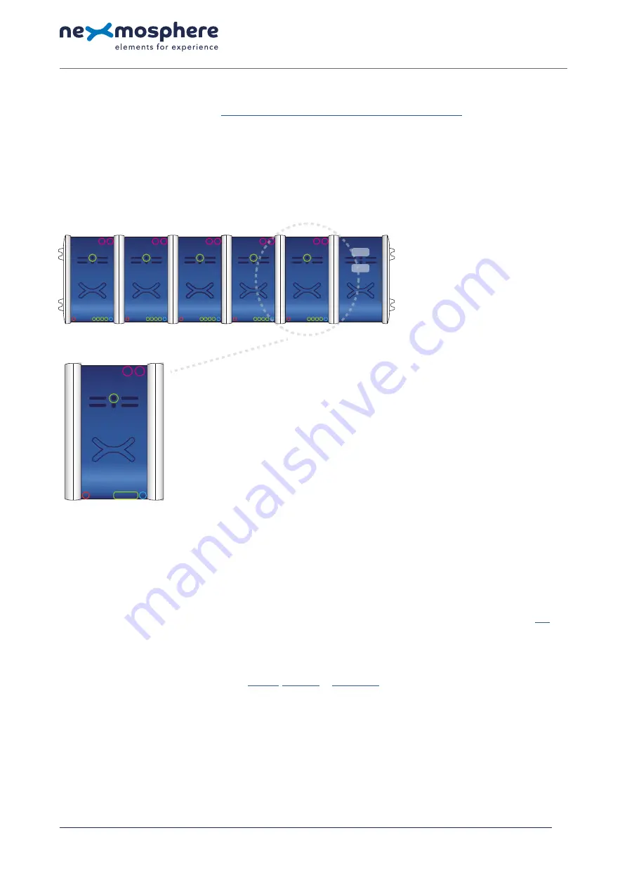
XM-350 with EM-F4 expansion
The XM-350 is an Xperience controller with 1 X-talk interface. It can be expanded at our factory with up to 5 EM-F4 modules.
An EM-F4 module has 4 Wireless X-talk channels to which
XF-P3 sensors
can be paired. The API address of a Wireless X-talk
channel is determined by adding the number of the channel to the base address of the EM module. For example, for channel
3 of the EM-F4 module closest to the XM-controller, the API address is 113
.
Hardware setup
1.
Connect an Element to the X-talk interface on the XM-350 module (optional).
2.
Connect a serial cable* to the API interface and to a 3rd party device (e.g. Mediaplayer or PC).
3.
Connect a 5VDC power supply to the DC power socket on the XM-350 module.
4.
Wait until the green status LED on the XM-350 controller stops blinking. This lasts about 10 seconds.
5.
Pair one or more XF sensors to any of the Wireless X-talk channels. See page 2 for step-by-step pairing procedure.
*Nexmosphere has 2 serial cables available which are compatible with the XM-350:
CA-9J9B
(RJ9 to 3.5mm jack) and
CA-9D9B
(RJ9 to DB-9).
Next to these serial cables, a compatible Serial-to-USB cable is also available:
CA-9U9B
(RJ9 to USB-A). The driver for this cable can be downloaded
here
.
Software setup for testing (Terminal)
Typically, the XM-350 controller is connected to a 3rd party device, such as a Digital Signage Player, on which CMS software is installed which has built-in
functionality for sending and receiving Serial Events. However, if you want to do a first test on a PC or Mac, follow the instructions below:
1.
Download a terminal program. For example
Termite
,
Hercules
or
SerialTools.
2.
Open the Terminal program and go to settings. Choose the COM port to which the XM-350 controller is connected*.
3.
Set the COM port settings to the following values
Baudrate
115200
Flow Control
None
Parity
None
EOL
CR+LF
Data
Bits
8
Protocol
ASCII
Stop
Bits 1
4.
Set the COM port to “Open”.
The controller is now ready for use.
5.
When sending consecutive API serial commands to the XM-350 controller, place a 75mS delay between each command.
*
In case the XM-350 controller is connected via a Serial-to-USB cable or adapter, typically this is the highest available number in the COM port drop-down setting.
N ex m o s p h e re
Le H av re 1 3 6
5 6 2 7 SW E i n d h ove n • T h e N e t h e r l a n d s
T
+ 3 1 4 0 2 4 0 7 0 7 0
E
s u p p o r t @ n ex m o s p h e re.c o m
QUICK START GUIDE
XM-350 XPERIENCE CONTROLLER WITH EM-F4 EXPANSION
© 2020-2021 Nexmosphere. All rights reserved. v2.0 / 06-21
All content contained herein is subject to change without prior notice.
1
11X
12X
13X
14X
15X
00X
1
API
SB
5V
SD
LED
ERR
XM-350
EM-F4
EM-F4
EM-F4
EM-F4
EM-F4
1
A
B
P
E
2
3
4
1
A
B
P
E
2
3
4
1
A
B
P
E
2
3
4
1
A
B
P
E
2
3
4
1
A
B
P
E
2
3
4
1
A
B
P
2
3
4
E
S
S
S
S
S
S
1.
X-talk interface 001
5V.
5VDC Power input (2.5mm DC)
SB.
ShopBus interface (RJ25)
API.
API interface (RJ9 )
SD.
SD card slot for bootloading
LED.
Green status LED
1
Status LED (green) Wireless X-talk channel xx1
2
Status LED (green) Wireless X-talk channel xx2
3
Status LED (green) Wireless X-talk channel xx3
4
Status LED (green) Wireless X-talk channel xx4
A
Control button A
B
Control button B
S
Status LED (green)
P
Pair LED (blue)
E
Error / Unpair LED (red)


