


7
FORM NO. L-21204-D-0419
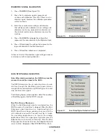
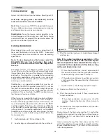
ELECTRICAL CONNECTIONS
Figure 4
Electrical Connections
* Power cable must be less than 10 m [390 in].
** There are two terminals that require a low impedance connection
to earth ground.
† For improved signal integrity in noisy environments, tie cable
shields directly to Earth Ground.
46
45
44
43
42
41
40
39
38
37
36
35
34
33
32
31
30
29
28
27
26
25
24
Control Signal Shield & Earth Ground** †
Control Signal Common
Splice B Input
Splice A Input
Run/Stop Input
Signal Shield †
Common
Remote Tension Setpoint Input
+12 VDC Excitation
Common
Diameter Sensor Input
+24 VDC Excitation
Load Cell Shield †
Excitation Common
+6 VDC Excitation
–Sensor Signal
+Sensor Signal
Excitation Common
+6 VDC Excitation
–Sensor Signal
+Sensor Signal
+24 VDC
Common
Earth Ground**
Alarm 1 Out
Alarm 2 Out
Alarm Common
† Alarm Shield
0-10 VDC
Output Common
4–20 mA
Output Common
† Signal Shield
0–10 VDC
Output Common
4–20 mA
Output Common
† Signal Shield
1
2
3
4
5
6
7
8
9
10
11
12
13
14
15
16
17
18
19
20
21
22
23
R
S
TC
USB
Control
Inputs
Power
Input*
Control
Output B
Control
Output A
Load
Cell 1
Load
Cell 2
Power Indicator
Reset
Network Port and
Indicators