Nexen RSTC1000 User Manual Download Page 26

FORM NO. L-21204-D-0419

26

TROUBLESHOOTING

Problem

Probable Cause

Diagnosis Test

Corrective Action

Power Indicator is not
illuminated.

No power

Check for 24 VDC across

terminals 1 and 2 using a
voltmeter.

Restore 24 VDC.

Control inputs do not
respond.

Improper or missing signal

Measure the voltage at inputs
41, 43 and 44.

Correct any problems with

voltage or wiring using the
SPECIFICATIONS section to
determine proper range.

RSTC will not go
into Auto mode.

Run signal not provided to

control input or software
command not given

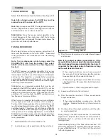
Start machine and watch for

Run/Stop to go high on
Diagnostics window.

Check Run/Stop input wiring or
control panel to make sure the
command is sent properly.

Run/Stop signal not set up
properly

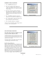
Check Run/Stop configuration
in Signal Calibration window.

Refer to Signal Calibration

section of manual and select

proper configuration.

RSTC in manual mode

Check Automatic/Manual
button on Diagnostics window.

Switch to Automatic using
Automatic/Manual button or

issue Automatic command from

control panel.

Tension fluctuates in
automatic mode.

Improper settings or

calibration

Tension not fluctuating in

manual mode indicates a
problem with RSTC.

Re-tune RSTC.

Recalibrate load cells.

Web machine problem

Fluctuating tension in manual
mode indicates a machine
problem.

Correct problem with web
machine.

Output goes to 0% during
unwinding roll
acceleration.

Machine acceleration rate too
high

Decrease acceleration rate and

see if output % increases
above 0%.

Decrease machine acceleration

as roll inertia limits acceleration

rate of machine.

Output goes to 0% and

tension rises above
setpoint when roll unwinds
at constant web speed.

Acceleration of the unwinding

roll shaft causing tension
increase

Decrease web speed as roll

diameter approaches core to
see if output increases above 0.

Decrease web speed as roll

diameter approaches core
because roll and shaft inertia
cause tension to increase
above setpoint.

Output goes to 100%
during deceleration and

tension falls below
setpoint.

Machine deceleration rate is

too high and there is not
enough torque.

Decrease deceleration rate and

see if output stays below

100%.

Decrease machine deceleration

as roll inertia limits deceleration

rate of machine or increase

torque output of torque
actuator.

Output goes to 100% and

tension falls below
setpoint when roll winds
at constant web speed.

Not enough torque for the size

of roll and the tension setpoint

Decrease the tension setpoint
(increase taper) and see if

output stays below 100%.

Increase torque output of

torque actuator or decrease
tension setpoint or increase
taper.

Summary of Contents for RSTC1000

Page 1: ...FORM NO L 21204 D 0418 Tension Controller RSTC1000 WEB CONTROL PRODUCTS User Manual ...

Page 2: ...s unit should be installed operated and maintained by qualified personnel ONLY Improper installation can damage your system or cause injury or death Comply with all applicable codes DANGER Manufacturers Declaration In accordance with the CE machine directive 98 37 EC Appendix II B We hereby declare that the pneumatic mechanical components described in this manual as well as their indi vidual compo...

Page 3: ...nal Calibration 16 Tension Signal Calibration 16 Diameter Signal Calibration 17 Run Stop Signal Selection 17 Tuning 19 RSTC Tuning Window 19 Tuning Procedure 19 Setpoint 20 Advanced 20 Taper Tension 20 Network Port Setup 21 Operation 21 Manual Control 21 Unwind Application 22 Splicing Unwind Application 22 Wind Application 23 Splicing Wind Application 23 Spring Disengaged Clutch 24 Mid Process App...

Page 4: ... tension winding and taper tension winding RSTC1000 SYSTEM The RSTC1000 Tension Control System includes three components the RSTC1000 RSTC Operator Panel ROP and RSTC Communications Software The RSTC1000 tension controller can be used as a slave on a Modbus RTU network Because of this capability many Human Machine Interfaces HMIs and Programmable Logic Controllers PLCs can communicate directly wit...

Page 5: ... in order to stop electrical interference at the source See Figure 2 Isolate signal and sensor cables from cables carrying AC voltages power for high current loads or relays and solenoids Either relocate the signal and sensor cables away from other cables or use grounded metal conduits to shield them This will reduce the potential for noise interference between the signal and sensor cables and the...

Page 6: ... The RSTC can be mounted on 35 mm DIN rail or panel mounted Refer to Figure 3 CAUTION Mount the RSTC in a shock and vibration free area with an ambient temperature of less than 140 F 60 C and more than 32 F 0 C 149 0 5 87 110 3 4 34 13 9 0 55 13 9 0 55 35 0 1 38 75 0 2 95 134 1 5 28 7 4 0 29 7 4 0 29 1 1 0 04 2X 60 2 2 37 R2 2 0 09 4X ...

Page 7: ...Input Signal Shield Common Remote Tension Setpoint Input 12 VDC Excitation Common Diameter Sensor Input 24 VDC Excitation Load Cell Shield Excitation Common 6 VDC Excitation Sensor Signal Sensor Signal Excitation Common 6 VDC Excitation Sensor Signal Sensor Signal 24 VDC Common Earth Ground Alarm 1 Out Alarm 2 Out Alarm Common Alarm Shield 0 10 VDC Output Common 4 20 mA Output Common Signal Shield...

Page 8: ...t Tied to PLC Input Alarm Output Tied to External Inductive Coil Alarm Common Alarm Out Alarm Common RSTC Alarm Out Alarm Common NOTE The minimum value of Resistor R is equal to VDC divided by the maximum current limit of the Indicator Maximum current limit of the indicator must be less than the current limit of the alarm output See Specifications for maximum current NOTE Be sure the current requi...

Page 9: ...in Guage Load Cell 24 25 26 27 28 29 30 31 32 33 34 Sensor B R W G Cable Shield Add CFL Sensor Colors Vex Vex Vsig Vsig Figure 6 Control Input Signals NOTE To isolate the Control Input Signals use a power supply that is separate from the RSTC power supply Figure 8 Load Cell Connections 40 41 42 43 44 45 46 Cable Shields 12 to 24 VDC DC Common Run Stop Splice A Splice B 32 33 34 35 36 37 38 39 1 5 ...

Page 10: ...5 Connections DC Common TxB TxA RxB RxA 1 2 3 4 5 6 DC Common RxB RxA TxB TxA LTR RSTC1000 PLC or HMI Four Wire RS485 Connections LTR DC Common TxB TxA RxB RxA 1 2 3 4 5 6 DC Common Non Inverted Tx Rx Inverted Tx Rx RSTC1000 PLC or HMI Two Wire RS485 Connections 24 VDC DC Common TxB TxA RxB RxA 1 2 3 4 5 6 Red Black White RxB Yellow RxA Blue TxB Orange TxA RSTC ROP ROP RSTC LTR Termination resisto...

Page 11: ... alarm cable shield to chassis ground Control Outputs The Control Output signal is used to change the torque output of a pneumatic brake or clutch via an electro pneumatic converter or a motor drive system for the purpose of controlling tension There are two channels of control outputs Control Output A and Control Output B Each channel has a 0 10 VDC and 4 20 mA output signal All Control Outputs a...

Page 12: ...lations when the web does finally move Splice A B When 12 24 VDC is applied to one of these digital inputs for at least 100 milliseconds the RSTC will respond by resetting Adaptation to a level determined by SPLICE ADAPTATION The RSTC will also make the cor responding Control Output active and the other standby The 12 24 VDC signal can be momentary or maintained however only one Splice Input can h...

Page 13: ...onnect the USB cable between computer and RSTC Refer to Figure 11 4 Turn on 24 VDC power supply Power indicator will be on Refer to Figure 11 Note Refer to the RSTC Communications Software Help menu for instructions on navigating the program and accessing its functions The steps below describe using the functions to configure the RSTC DISPLAY WINDOW Select the DISPLAY icon from the toolbar See Fig...

Page 14: ...Actuator Selection Screen TORQUE ACTUATOR Actuator Select from the Torque Actuator drop down menu the type of actuator the RSTC will control Actuator Inertia Enter the rotor inertia of the brake or clutch in the designated imperial or metric units The choice of units is determined by selecting the DISPLAY icon and then selecting Imperial or Metric in the UNITS pane Inertia values for Nexen Brakes ...

Page 15: ...p roller diameter Min Core Diameter Enter in the minimum core diameter that will be used For mid process tension control applications enter the diameter of the nip roller Avg Web Width Enter in the average web width maximum width minimum width 2 Material Select the web material to be used Paper or Plastic Steel or Aluminum from the drop down menu See Figure 16 OUTPUTS Minimum Output Used to specif...

Page 16: ...es for converting load cell output voltages into tension values These calibration sets can be used for different web paths that utilize the same set of load cells and have different web wrap angles 1 Press TENSION See Figure 18 2 Under Calibration Set 1 enter the web tension that will be used to calibrate the span condition into the SPAN TENSION box Span Tension is equal to the weight as shown in ...

Page 17: ...se the Adaptive Gain will increase to maximum After the Run Stop signal transitions back to low the Adaptive Gain will return to Initial Adaptation See OPERATION section Figure 21 Run Stop Signal Selection Screen Figure 20 Diameter Calibration DIAMETER SIGNAL CALIBRATION 1 Press DIAMETER See Figure 20 2 Press Yes if a diameter signal is present and continue with calibration Press No if there is no...

Page 18: ...goes high otherwise the Adaptive Gain will increase to maximum After the Run Stop signal pulses high a second time the Adaptive Gain will return to Initial Adaptation as the RSTC assumes the machine has stopped See OPERATIONS section Run Pulsed Encoder The first time a machine driven encoder pulses Run Stop input the RSTC algorithm will begin adapting to account for the roll s diameter and inertia...

Page 19: ...ptive algorithm that is user tuned After tuning the algorithm will automatically adapt internal gain values to account for changes in roll diameter and inertia This algorithm is modeled after unwinding and winding applications which results in an non linear adaptation process that closely follows the actual changes occurring in a web machine Stabilization is an important variable that must be set ...

Page 20: ... as the splice process usually involves larger rather than smaller rolls The idea is that the adaptation Remote SP Select ON to enable tension setpoint by external analog signal See INPUT OUTPUT DESCRIPTIONS section or OFF to disable this feature When enabled tension setpoint changes from all other sources are ignored TAPER TENSION During winding applications it is often necessary to re duce the t...

Page 21: ...C Device Address Specify the device address required by the Modbus master device If connecting to Nexen s RSTC Operator Panel select 24 Port Settings select to update the settings immediately or the next time the RSTC is powered on OPERATION MANUAL CONTROL Manual control of the RSTC s control output is useful for troubleshooting The AUTOMATIC MANUAL button of the OPERATION MODES pane in the DIAGNO...

Page 22: ...n Figure 28 UNWIND APPLICATION A typical unwind application begins with a new full roll To insure that the web tension reaches setpoint as quickly as possible the Splice signal can be used to reset Adaptation to a higher level set by SPLICE ADAPTATION before the machine starts This shortens the time it takes for the RSTC1000 to adapt its gains to the new roll If a Splice signal is not used the web...

Page 23: ...l as specified by Standby Output Acceleration Acceleration Run Speed Run Speed Deceleration Deceleration Stopped Run Stop Signal Web Speed Splice Signal Splicing Adaptation Initial Adaptation Small Roll Large Roll Adaptation Figure 29 WIND APPLICATION A typical winding application begins at core The INITIAL ADAPTATION value should be set high enough to allow the tension setpoint to be reached quic...

Page 24: ...sired and decrease when less tension is desired SPRING DISENGAGED CLUTCH It is common to use a spring disengaged clutch on a winder and this spring can affect performance if the RSTC s output becomes too low and the clutch begins to disengage Use the MINIMUM OUTPUT setting to keep the control output high enough to overcome the spring force in a spring disengaged clutch DIAGNOSTICS Select DIAGNOSTI...

Page 25: ... 24 VDC 140 mA max current sinking Control Inputs 12 24 VDC 20 mA max ANALOG SIGNALS Diameter Sensor Input 0 12 VDC Remote Tension Setpoint Input 0 12 VDC Load Cell Inputs 2 channels 0 1 VDC Control Output 1 0 10 VDC and 4 20 mA Control Output 2 0 10 VDC and 4 20 mA SENSOR EXCITATIONS Load Cell Excitation 6 VDC Other Sensor Excitations 24 VDC 100 mA max 12 VDC 60 mA CERTIFICATIONS Certification CE...

Page 26: ...rate load cells Web machine problem Fluctuating tension in manual mode indicates a machine problem Correct problem with web machine Output goes to 0 during unwinding roll acceleration Machine acceleration rate too high Decrease acceleration rate and see if output increases above 0 Decrease machine acceleration as roll inertia limits acceleration rate of machine Output goes to 0 and tension rises a...

Page 27: ... in3 where p aluminum 0924 p cast iron 260 p steel 282 Calculate the inertia of complex concentric rotating parts by breaking the part into simple cylinders calculating the inertia or each and summing the values WK2 W R2 2 D L Dia in WK 2 lb ft 2 Dia in WK 2 lb ft 2 Dia in WK 2 lb ft 2 0 750 0 00006 7 500 0 6110 13 250 5 9600 1 000 0 0002 7 750 0 6990 13 500 6 4200 1 250 0 0005 8 000 0 7910 13 750...

Page 28: ...ATURE WHATSOEVER WHETHER ARISING OUT OF BREACH OF WARRANTY OR OTHER BREACH OF CONTRACT NEGLIGENCE OR OTHER TORT OR OTHERWISE EVEN IF NEXEN SHALL HAVE BEEN ADVISED OF THE POSSIBILITY OR LIKELIHOOD OF SUCH POTENTIAL LOSS OR DAMAGE For all of the purposes hereof the term consequential damages shall include lost profits penalties delay damages liquidated damages or other damages and liabilities which ...

Reviews: