


Copyright © 2017 NEXCOM International Co., Ltd. All Rights Reserved.
21
eLITE610 User Manual
Chapter 2: Jumpers and Connectors
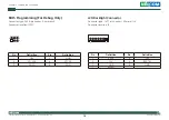
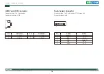
LED Connector
Connector type: 1x5 5-pin header JST, 2.0mm pitch
Connector location: J1
5
1
Pin
Definition
Pin
Definition
1
HDDLED#
2
VCC5
3
GND
4
Standby Power 5V
5
Power LED 5V
Remote Control Connector
Connector type: 1x3 3-pin header, 1.25mm pitch
Connector location: JP10
Pin
Definition
1
ATX_PWRBTN#_RE
2
GND
3
SOC_SLP_S3_N_RE
3
1