background image

26 Software 

Application 

2.  Connect the USB cable to the Controller and Power it on. 

3.  Start the application by double-clicking on the newly created Smart 

Table-Util icon in Start->Programs->Newport->Smart Table Controller 
folder. 

The SmartTable-Util application has five (5) main tabs: About, Status, Auto-
tune, Manual Tune and Options.  The features available in these tabs are 
explained in the following sub-sections. 


5.1.1 About 

Tab 

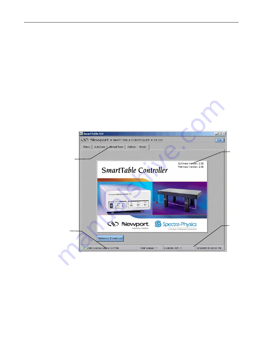
When the application is opened, it will default to the “About” tab.  It will 
also start communication with the controller connected to USB interface.  
The application and controller firmware version numbers are displayed on 
this screen. 


Software and 
Firmware Versions

Smart Table 
Utility Function 
Tabs 

Bottom Bar is 
common to all the 
screens 

Mouse over some 
buttons will reveal 
Tool Tips for ease 
of use 

Figure 18  About Tab Screen 

Click on “Firmware Download” button to update the controller’s firmware.  
The software will prompt the user to select a “DSP Firmware File at the 
beginning of the firmware download process”.  This file has an “FWR” 
extension, and is located in the Firmware subdirectory by default.  Once this 
file is selected, the application will initiate the download process.  This 
process consists of the following steps: 

• 

Erase Firmware:  At this stage, the controller’s existing firmware is erased 

from its non-volatile flash memory. 

Summary of Contents for Spectra-Physics ST-200

Page 1: ...Smart Table ST 200 User s Manual...

Page 2: ......

Page 3: ...y to products which have been repaired or modified without Newport s written approval or products subjected to unusual physical thermal or electrical stress improper installation misuse abuse accident...

Page 4: ...efforts to ensure that all its personnel protect the Newport Programs as trade secrets of Newport Corporation Customer shall not at any time disclose Newport s trade secrets to any other person firm...

Page 5: ...with the RMA and we will either repair or replace it at our discretion Newport is not responsible for damage occurring in transit and is not obligated to accept products returned without an RMA E mai...

Page 6: ...ame or Chassis 10 1 1 7 On 10 1 1 8 Off 11 1 1 9 Protective Conductor Terminal 11 1 1 10 USB Connector Symbol 11 1 1 11 Mounting precaution 11 1 2 Warnings and Cautions 12 1 2 1 General Warnings 12 1...

Page 7: ...5 1 5 Options Tab 31 6 Maintenance and Service 33 6 1 Enclosure Cleaning 33 6 2 Fuse Replacement 33 6 3 Obtaining Service 34 6 4 Service Form 35 List of Figures Figure 1 General Warning or Caution Sy...

Page 8: ...Screen 27 Figure 20 Auto Tune Tab Screen showing dual channel display 29 Figure 21 Auto Tune Tab Screen showing single channel display 29 Figure 22 Manual Tune Tab Screen 30 Figure 23 Options Tab Scr...

Page 9: ...where personal injury or damage to the equipment is possible 1 1 2 Electric Shock Figure 2 Electrical Shock Symbol The Electrical Shock Symbol in the figure above appears throughout this manual This s...

Page 10: ...5 Fuse Symbol The fuse symbol in the figure above identifies the fuse location on the Smart Table Controller 1 1 6 Frame or Chassis Figure 6 Frame or Chassis Terminal Symbol The symbol in the figure...

Page 11: ...external protective earthing system through the power cord 1 1 10 USB Connector Symbol Figure 10 USB connector Symbol The USB connector symbol in the above figure identifies the location of the USB co...

Page 12: ...ipment Heed all warnings on the unit and in the operating instructions Do not use this equipment in or near water This equipment is grounded through the grounding conductor of the power cord Route pow...

Page 13: ...ing power Do not block ventilation openings Use only the specified replacement parts Follow precautions for static sensitive devices when handling this equipment This product should only be powered as...

Page 14: ...14 Safety Precautions This page is intentionally left blank...

Page 15: ...tted to the table from the floor Although excellent isolation from floor vibration can be achieved in these systems the table will deviate from the ideal rigid body behavior at natural frequencies of...

Page 16: ...ng surface and composite edge finish Mounting Holes 1 4 20 holes on 1 in grid M6 1 0 holes on 25 mm grid 0 5 in borders 12 5 mm borders Hole Core Sealing Easy clean conical cup 0 75 in 19 mm deep Non...

Page 17: ...assively damped Newport RS series table The dampers are installed at two corners of the table adjacent to a long side The exact position of each damper is indicated by three flat head screws that are...

Page 18: ...rrent continuous output rating 12V 5 0 6A 0 7A Table 2 Smart Table Controller Specifications System Environmental Specifications AC Input 100 240VAC 10 47 63Hz 1 25A 80W Operating Temperature 5 C to 4...

Page 19: ...or mishandling Inspect the contents for damage If there is visible damage to the instrument upon receipt inform the shipping company and Newport Corporation immediately WARNING Do not attempt to opera...

Page 20: ...fied electrician verify the wall socket that will be used is properly polarized and properly grounded Provide adequate distance between the Smart Table Controller and adjacent walls for ventilation pu...

Page 21: ...front panel that allows the user to operate the system as well as provide system status The front panel is shown in Figure 14 below Outputs 1 and 2 Power Switch Auto Tune Button USB Port Status LEDs...

Page 22: ...l operation GREEN GREEN 13 Channel 1 Disabled Channel shutdown via software OFF GREEN 14 Channel 2 Fault Damper not connected GREEN 15 Channel 2 Fault Channel shutdown due to Damper Fault GREEN 16 Cha...

Page 23: ...to repeat the process Beeping or tonal sounds can be heard from the dampers during the auto tuning process Please have in mind that during the auto tuning process the table may experience higher vibr...

Page 24: ...Frame or Chassis Terminal Voltage setting Fuse Model Number Label Channel 2 Damper Output Connector Channel 1 Damper Output Connector Figure 16 Rear Panel 4 2 1 Damper Output connectors Two 15 pin co...

Page 25: ...USB cable to the controller for the first time 1 Minimum requirements for the computer are A personal computer with a 486DX or higher processor Microsoft Windows 98 operating system or Microsoft Windo...

Page 26: ...ication and controller firmware version numbers are displayed on this screen Software and Firmware Versions Smart Table Utility Function Tabs Bottom Bar is common to all the screens Mouse over some bu...

Page 27: ...er outage unplugged USB cable during the firmware download process 5 1 2 Status Tab A few seconds after the About screen appears the application will switch to the Status Tab Figure 19 Status Tab Scre...

Page 28: ...hannels and measure vibration levels over a period of 500ms The data will be averaged over several time frames Number of averages can be set on the Options tab Section 5 1 5 2 Both un damped and dampe...

Page 29: ...Software Application Figure 20 Auto Tune Tab Screen showing dual channel display Figure 21 Auto Tune Tab Screen showing single channel display...

Page 30: ...e tuning the loop gains Click on Apply Changes button in order for the application to send the desired loop gains to the controller and save them in the controller s non volatile flash memory In case...

Page 31: ...ally Low Medium and High control loop gain margins Specify the desired percentage by which control loop gain has to be reduced at the end of auto tuning process The gain stability margin and the contr...

Page 32: ...d if the payload operation involves high vibration levels for short periods of time 5 1 5 4 Miscellaneous Click on Apply Settings button in order for the application to send any changes made on this t...

Page 33: ...ore cleaning the enclosure of the Smart Table Controller the AC power cord must be disconnected from the wall socket The enclosure may be cleaned with a soft cloth dampened with either a mild soapy wa...

Page 34: ...rt Corporation for service 6 3 Obtaining Service The Smart Table Controller contains no user serviceable parts To obtain information regarding factory service contact Newport Corporation or your Newpo...

Page 35: ...tain RA prior to return of item Address ________________________________ ____________________Date _________________ Country _______________________ Phone Number ______________________________________...

Page 36: ...Newport Corporation Worldwide Headquarters 1791 Deere Avenue Irvine CA 92606 In U S 800 222 6440 Tel 949 863 3144 Fax 949 253 1680 Internet sales newport com Visit Newport Online at www newport com...

Reviews: