4.
Alignment and Measurement
4.2.
Starting a Measurement
4.2.1.
Alignment of the Input Beam
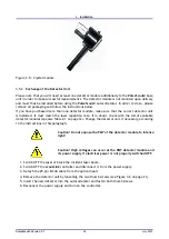
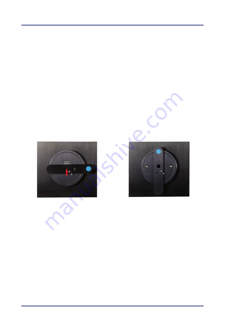
Set the variable alignment aperture to alignment position (see Figure 4.2). Align the input beam,
using two optical elements (glass plate, mirror, etc.) through the aperture into the optical head
while maintaining normal incident between the
Pulse
Scout2
and the input beam. It is very impor-
tant that the beam is parallel to the optical table and perpendicular to the input aperture of the
Pulse
Scout2
optical head. The better these conditions are met the easier it is to adjust the optical
head in the following steps. Ensure that the input beam power is below the maximum input power
for the
Pulse
Scout2
(see Table 2.1 on page 12 for speci cations), and that the polarization of the
input beam is horizontal and nearly collimated.
Although the sensitivity is much higher, for most con gurations the average input power can be
up to 250 mW without danger of damaging the system. However, if it is not stated explicitly for
your device, be careful when using con gurations for low repetition rates and high energy laser
(ampli er) systems! For such con gurations it is strongly recommended to keep the input pulse
energy below 1
µ
J to avoid damage of the autocorrelator. Once an autocorrelation signal is found
the input power should always be lowered while maintaining a suf cient autocorrelation signal on
the
scout
Link
Control Software.
Figure 4.2.: Alignment aperture (arrow) in alignment position and in normal measurement posi-
tion.
The beam should enter through the input aperture of the autocorrelator nearly perpendicularly to
the unit.
For ease of alignment, ensure that the beam distance is set to the non-collinear position and that
the height of the optical head is adjusted parallel to the optical table.
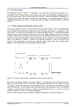
Align the input beam through the alignment aperture to achieve a beam position similar to the one
shown in Figure 4.3, non-collinear mode. Both beam re ections should be at the same height and
the right re ection should be aligned onto the cross-hair within the alignment window.
Tweaking the optical assembly in the horizontal plane will move the back re ection in the hori-
zontal plane and tilting the optical assembly up or down with the third leg will move the back
re ection up or down.
Pulse
Scout2 Version 1.1
23
July 2015


