30
Theory of Operation
3.5.1
USB
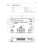
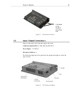
The USB input is a Micro-AB connector. Use a Micro-B to USB-A cable to connect
the 8742 Controller/Driver to a computer.
3.5.2
Ethernet
The Ethernet input is a standard RJ-45 connector. Use a Cat 5 Ethernet cable to
connect the 8742 Controller/Driver to a router, an Ethernet switch, or a computer.
3.5.3
RS-485
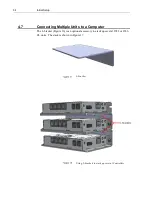
There are two RS-485 connectors that accept standard 3.5mm stereo plugs. The two
connectors are connected in parallel inside the Model 8742. (The wiring convention
is TIP = D+, RING = D-, SLEEVE = GND.) These connections are used to simplify
the wiring between an external computer and multiple 8742 or 8743-CL
Controller/Driver units.
See Section 4.7.3 Using RS-485 LAN to Daisy-Chain and Section 5.5 RS-485
Communication for more information on setting up these configurations. See the
Accessories Section 2.4 for information on an RS-485 cable that will facilitate
normal multi-unit linking.
3.5.4
Power
There are two power inputs that can take a standard barrel connector with the output
diameter 5.5 mm and internal diameter 2.1 mm. The provided power supply can be
plugged in either of these two connectors. The other connector is used to link the
power supply to another 8742 Controller/Driver. See the Accessories Section 2.4
for information on the Power supply link cable.
Use the power switch to turn the unit ON and check the LED status as described in
Section 3.3.
3.5.5
Picomotor Interfaces
Each 8742 can drive up to 4 Picomotors, one motor at a time. Before connecting,
inspect the Picomotor cables, connectors and generally their integrity. The
Picomotors will receive high voltage pulses that can be dangerous if wires are
exposed. Contact New Focus if you see any problems.
Do not connect anything else to the 8742 outputs. The Controller/Driver is designed
to handle only New Focus standard Picomotors. If the output is shortened or
otherwise misused, an internal component will open and the unit will have to be
serviced.
Summary of Contents for New Focus Picomotor 8742
Page 1: ...Picomotor Controller Driver User s Manual Model 8742 ...
Page 53: ...Computer Interfacing 53 Cycle Tab Cycle Motion ...
Page 54: ...54 Computer Interfacing Terminal Tab Command Line Terminal ...
Page 57: ...Computer Interfacing 57 Options Window Connection Options Setup ...
Page 58: ...58 Computer Interfacing Properties Window USB and Ethernet Properties ...
Page 59: ...Computer Interfacing 59 Controller Scan Scan RS 485 LAN ...
Page 61: ...Computer Interfacing 61 Device Address Window View Change Controller Address ...


