background image

-4-

Electrical Code, and with the regulations in C.S.A. Standard B365 “The Installation Code for Solid Fuel Burning 

Appliances  and  Equipment”  in  Canada.  In  the  U.S.,  this  furnace  must  be  installed  according  to  NFPA-211, 

“Standard for Chimneys, Fireplaces, Vents, and Solid-Fuel Burning Appliances”.

The flue pipe must be black 24 ga pipe minimum.

Flue pipe connections must be secured with metal screws and have as few elbows as possible. This furnace 

should be installed by a qualified furnace serviceman.

CAUTION:

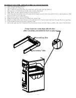
 The flue collar is sized so that a trade size flue pipe fits snugly inside it. Joints in flue pipes, including 

the connection at the appliance and the chimney, shall have at least 30 mm (1 3/16 inch) over lap. Flue pipe 

connections must be secured with at least 3 metal screws or an equivalent mechanical means; and be made 

tight in accordance with good practice.

The flue products may contain carbon monoxide particularly when the wood fire is being starved for air (made 

to burn at slow rate). Therefore, the flue pipe must seal tight and must not be inserted into the return air stream of 

the circulating blower.

Wood storage should conform to local bylaws, and should not be within minimum clearances for combustible 

surfaces as shown above.

NOTE: COMBUSTION AIR is Where fans are used in the fuel storage area, they should be installed so as not to 

create negative pressures in the room where the solid fuel burning appliance is located.

OUTSIDE COMBUSTION AIR

Provision for outside combustion air may be necessary to ensure that fuel-burning appliances do not discharge 

products of combustion into the building. Guidelines to determine the need for additional combustion air or not 

may not be adequate for every situation. If in doubt, it is advisable to provide additional air.

Outside combustion air may be required if:

4. 

The solid-fuel-fired appliance does not draw steadily, experiences smoke roll-out, burns poorly, or back-drafts 

whether or not there is combustion present.

5. 

Existing fuel-fired equipment in the building, such as fireplaces or other heating appliances smell and do not 

operate properly, suffer smoke roll-out when operated, or back-draft whether or not there is combustion 

present;

6. 

Any of the above symptoms are alleviated by opening a window slightly on a calm (windless) day;

7. 

The building is equipped with a well-sealed vapor barrier and tight fitting windows and/or has any powered 

devices which exhaust building air;

8. 

There is excessive condensation on windows in the winter; or

9.  A ventilation system is installed in the building.

If these or other indications that infiltration air is inadequate, additional combustion air should be provided from 

the outdoors.

DUCT INSTALLATION

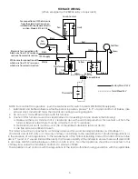
Not to be connected to ductwork that is still connected to another furnace. As the unit may be used as a gravity 

furnace when the power is off, the following is recommended:

1.  Locate the furnace as centrally as possible in the building so the best warm air distribution may be enjoyed.

2.  Use an extended plenum (central duct) at least one size larger than called for in National Warm Air Standards.

3. 

Use a minimum pipe size of six inches diameter in runs and in no case smaller than five inches diameter.

4. 

Slope extended plenum’s and runs as much as possible to facilitate gravity flow of warm air.

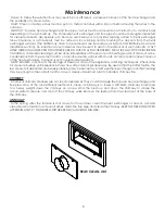
BELT TENSION (FOR BELT DRIVE BLOWER MOTORS)

When adjusting to the proper pulley setting make certain that the belt is able to flex approximately one inch 

without movement of the motor pulley.

IMPORTANT: This furnace must have a MINIMUM return air duct size equal to 250 sq. in. and a MINIMUM supply air 

duct size equal to 180 sq. in. The supply air extended plenum should extend 8 – 10 feet out from the furnace, then 

gradually transitioned to the end of the duct system to provide a .20” W.C. static pressure.

HUMIDIFIER

Install  the  humidifier  in  the  return  air  plenum.  This  prevents  possible  damage  due  to  excessive  temperatures 

when there is a power failure.

Metal connecting ducting from the warm air plenum is recommended rather than plastic ducting.

Summary of Contents for WFA-85

Page 1: ...WFA 85 WFA 85E All installations must be made in accordance with local and provincial or state codes which may differ from the manual FOR COMMERCIAL USE ONLY USA ONLY NOTICE READ THESE INSTRUCTIONS SA...

Page 2: ...rect drive motor refer to the Motor Installation Guide A fan center is required to isolate motor leads and to control continuous low speed operation from the thermostat Select the motor heating speed...

Page 3: ...mper with this furnace 3 Caution If this furnace is used as a replacement for an existing furnace observe the following a Make sure there is a minimum of 6 clearance above the warm air plenum as far a...

Page 4: ...k drafts whether or not there is combustion present 5 Existing fuel fired equipment in the building such as fireplaces or other heating appliances smell and do not operate properly suffer smoke roll o...

Page 5: ...of wood being burnt Slide plate B should be open when burning wood When the firebox gets full of ash within two inches of door level some morning before loading the firebox push or rake the coals to t...

Page 6: ...red temperature It is very important to keep the secondary flames burning to maximize heat output and minimize air pollution so some experimentation will be necessary because each installation is diff...

Page 7: ...box Do not use additional grates or andirons to support the fire as these may create excessive heat PREPARATION AND STORAGE OF FUEL Solid fuel should be cut and split prior to the heating season and s...

Page 8: ...m the summer months or any other source will mix with the ash or creosote and cause corrosion of the heat exchanger Corrosion is not covered under warranty NOTE Establish a routine for the storage of...

Page 9: ...clearances Do not use salt wood driftwood gathered from the seashore Return air ducts are to be metal not wooden TO PREVENT DAMAGE Do not set the flue draft above 05 W C as the fire could burn out of...

Page 10: ...should hold brick lock up to correct height 4 Install brick by starting at front putting one 1 bottom brick in place then slide one 1 top brick in place Repeat this procedure going down both sides an...

Page 11: ...at exchanger move the front towards the door opening and pull the tube out of the secondary box 7 Remove through the door opening 8 Repeat the previous steps for the other secondary tube 9 Reach in an...

Page 12: ...102013 PRT SECONDARY AIR SLIDE PLATE SECONDARY AIR INLET FIREDOOR SLIDE PLATE DAMPER PRIMARY AIR INLET DRAFT CONTROL SLIDE PLATE FAN AND LIMIT CONTROL WIRING CONTROL CHANNEL EXHAUST GASES SMOKE PIPE A...

Page 13: ...Blue Black wire is TEW 14 1 Yellow wire is TEW 18 7 Blower wire is SPT 3 From insert Blue wire to fan terminal White wire to N terminal Red line to terminal Without Insert White 120V supply to N term...

Page 14: ...s used WHY THIS CONCERN ABOUT ALLOWING THE WOOD TO DRY Green or wet wood is undesirable for several reasons Green or wet wood tends to mildew and rot which causes a significant reduction in the therma...

Page 15: ...eosote is to leave the air inlet moderately open after adding wood until the wood is mostly reduced to charcoal and then close the inlet as much as desired This will promote complete combustion during...

Page 16: ...its air supply although both water and salt are sometimes suggested if a relatively airtight stove is the connected appliance This is easily done by closing the stove s air inlet dampers if all the st...

Page 17: ...4 03 590 96 Yellow Birch 3000 26 200 000 709 2 496 44 531 90 567 36 Elm 2750 24 500 000 662 8 463 96 497 10 530 24 Soft Maple 2500 24 000 000 649 2 454 44 486 90 519 36 Tamarack 2500 24 000 000 649 2...

Page 18: ...s furnace must be connected to a separate fused disconnect switch supplying power to the appliance The furnace must be suitably grounded 2 Install the BX cable containing three wires from the Electric...

Page 19: ...31 18 Place electrical unit directly into supply air of furnace Screw adapter in place for WFA 70 Interlock wire into junction box or front channel CAUTION Only one source of electrical supply shall...

Page 20: ...ectric thermostat to screw on 24V transformer Disconnect black wire on transformer from previous location Cut red between limit relay and connect black from transformer with red end For connection wit...

Page 21: ...21 Notes...

Page 22: ...ranty Brick Rack Top Frame 28160 1 F L Bracket Welded 610605 1 Baffle WAO D3090226 1 Firedoor Assembly 610649 1 Hinge Pin P626H 83485 4 Shovel Handle D3080161 1 Weld Scraper D4080112 1 Draft Control K...

Page 23: ...void the warranty SA Face Plate D3160623 1 Sec Air Back Plate D4060275 1 Front Gasket D2080001 1 G12 Delhi Blower Fan D2040103 1 Weld Formed Frame D4060194 1 Sec Air Slide D4060276 1 Front Panel 61063...

Page 24: ...D2020003 1 DRAFT FAN PACKAGE D4100105 1 PULLEY 3 1 4 X 1 2 VS MTR D2240001 1 Firedoor Spacer D2080003 1 Durolon Dovetail Gasket D2080002 1 Firedoor Liner D3160464 1 Firedoor Chute Weld D4060189 1 Inne...

Reviews: