background image


NL-8510 POS user manual


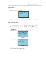
4.8 Hardware

Check hardware setting, shown as figure 4-13:


figure 4-13  

Check the customer series number; it must be identical to the one written on the back label.   

4.9 Communication


Communication setting is about setting the default communication method. Base on  

different kind of setting, applications use the API interfaces provided by BIOS firmware for 

retrieving relevant data. Applications use such data to determine the kind of communication 

is used for the POS.

Press Key “2”, a warning message will display, as shown in figure 4-14 


figure 4-14   

Press Key “enter” will go to the network equipment menu, as shown in figure 4-15 


figure 4-15   


――――

Warning

――――


This function is provided for 
specialist only.Press 

Enter

 to 

continue……  

――

Communication

――


1.WLM   2Modem 
3.thernet  4 None 
 

――

Hardware Setup

――


1.Serial No 

NL8510 supports 3 network options: wireless modem, wire modem and Ethernet;       

        wireless network option supports GPRS or CDMA.


36

Summary of Contents for NL-8510 POS

Page 1: ......

Page 2: ...2 5 Program download 8 3 The testing on functional modules 11 3 1 Version 12 3 2 Keyboard 13 3 3 Files 13 3 4 Magcard Test 14 3 5 Other card 15 3 5 1 IC SAM 15 3 5 2 MIFare Card 17 3 6 Printer 18 3 6...

Page 3: ...user manual 5 1 safety caution 37 5 1 1 Daily usage safety caution 37 5 1 2 Power 37 5 1 3 The Handling of Disused Products 37 5 2 Other Cautions 38 5 3 Install Printing Paper Important 38 5 4 Trouble...

Page 4: ...principles detailed description of functions PIN definition and the function of each interface settings and other relevant operation 2 2 Familiar with POS 2 2 1 unpacking Open the packing get the NL 8...

Page 5: ...ASCII characters GB18030 GB2312 Chinese Character and graphical document Keyboard 12 number alphabet keys 6 functional hot keys There are buttons of Up Down Menu 10 numbers 0 9 and ESC Backspace and...

Page 6: ...ess modem supports GPRS or CDMA Ethernet optional built in 10M Ethernet network function Printer Thermal printer can print graphics and many kinds of barcodes 58mm thermal print paper printing speed i...

Page 7: ...ing positive PIN4 GND ESD protection PIN5 GND ESD protection PIN6 Data receiving negative PIN7 GND ESD protection PIN8 GND ESD protection Serial Port 1 RS232 1 Function The main CPU s serial port 1 is...

Page 8: ...ata sending PIN2 DC output 5V PIN3 Null PIN4 Null PIN5 GND PIN6 Data receiving SAM card 1 Function The secondary CPU is directly connected to the SAM card and can read write the SAM card 2 The descrip...

Page 9: ...al PIN4 Null PIN5 GND PIN6 Null PIN7 ICC Serial Data IO PIN8 Null PIN9 Check if the Card is inserted PIN10 Power Output 5V for checking if the ICC is inserted SIM card Wireless 1 Function SIM card can...

Page 10: ...reason to let the POS fail to use can use startup and shut down to reboot the POS 2 4 Main Boot Menu and its functions Figure 3 1 is the factory default main menu within which Download Selftest and Ma...

Page 11: ...ou must enter the password 159951 Manage menu is for setting operating parameters For example the seventh option language you can choose Chinese or English Save this setting then all options language...

Page 12: ...to 320 kB Key Program will be downloaded into the key management program space up to 64 kB while normal files will be download into the flash file system space up to 2MB Adding a file for downloading...

Page 13: ...his function PinCode PinCode is the password for download Every maching is shipped with a default download password 159951 You can change the PinCode through the SETUP function of the POS If you chang...

Page 14: ...positioning and hardware repair We provide this self check program in the BIOS Using this program you can do all the manual testing on each of the POS sthe functional module self test 1 Version 2 Key...

Page 15: ...he size of FRAM if Ethernet is equipped the size of SRAM and the free space of SRAM if WLM wireless module is equipped for detail please see the figure 3 2 CPLD 0d OS 2 00 FRAM 8kB ETH YES SRAM 1M 512...

Page 16: ...st input number date and press enter LCD will display the number date and its length see figure 3 5 Next testing the input date see figure 3 6 input date then press enter to see the context and length...

Page 17: ...t document figure 3 7 File SELFTEST the three numbers represent File Length bytes File Start Block No and File Property A means common file document no encryption B means encrypted File Other File dis...

Page 18: ...r the menu shown as figure 3 9 Magcard Test 1 The 2 3 Track 2 The 2 Track 3 The 3 Track 4 The 1 2 3 Track Allow Input figure 3 9 Under this menu you can manually enter MagCard Number or Insert an ICC...

Page 19: ...hown as figure 3 11 Please press ESC To Cancel Other key To Retry PowerDown Succ figure 3 11 Press ESC will do the next card testing SAM4 also known as ESIM card during the testing will show that the...

Page 20: ...Under the menu shown as figure 3 10 press Key 2 to enter MIFare Card test Under the menu shown as figure 3 12 if the MIFare card is at the correct reading position press enter the LCD will display its...

Page 21: ...est Menu Figure 3 13 shows the main menu of Printer Test ____Printer Test____ 1 Single 2Multiple 3 Compress 4 Get Status figure 3 13 Printer Test Press Key 1 to do the single page test which means pri...

Page 22: ...r different testing page a submenu shown as figure 3 14 will show up This submenu is for selecting different print content 1 Test Paper 2 BlankPaper 3 Filled Paper 4 Erect stripe 5 Bill Paper 6 Contin...

Page 23: ...nt d Under the menu shown as figure 3 14 Press Key 4 to print a vertical strip page which looks like barcode e Under the menu shown as figure 3 14 Press Key 5 to print an invoice page f Under the menu...

Page 24: ...dem 2 Wireless modem 3 WLM_Dial Set 1 SYN Dial 2 ASYN Dial 1 Country setting 2 Dial 3 115200 test 4 ASYN test 5 Initializtion 6 Version 1 Response 2 Other commands 1 Reset 2 Version 3 Signal 4 AT resp...

Page 25: ...AUX1 Test 2 AUX2 Test 3 AUX Selftest Need Selftest equipment 4 AUX 1 2Direct Connect figure 3 17 Aux Port Test a Under the menu shown as figure 3 17 Press Key 1 and Key 2 to perform test on Aux Port...

Page 26: ...t on Aux Port 1 and Port 2 A Self Test Head is needed for each Aux Port to perform the self test c Under the menu shown in Figure 3 17 press Key 4 to perform Aux Port 1 and Aux Port 2 interlink test w...

Page 27: ...Baud Rate as POS s Baud Rate Set Port configuration as the POS ports connected with Input character into one of the serial tools the other serial tool should receive the same character Please refer to...

Page 28: ...check modem setting dialing number and TPUD press enter waiting for the dial up response If fail will display NO DIALTONE successful will display dial successful modem hand up Introduction dial number...

Page 29: ...5 Normal Mode 4 Huawei NAC ____ MODEM Test ____ Send Command From PC serial Port BPS115200 DB8 SP1 NP Press ESC To Exit figure 3 25 Operation method Enter the interface of wire modem test open the ser...

Page 30: ...rier wave lost time is 0 1s Under the menu shown as figure 3 23 press Key 6 to enter Check modem version menu shown as figure 3 27 ___ MODEM VER ___ CONEXANT CX86501 33600 V34 SDLC V2 02 ____ Init MOD...

Page 31: ...The following will describe the PPP operation process of wire MODEM figure 3 29 a Under the menu shown in figure 3 29 Press Key 1 to open PPP communication The whole communication process will be hand...

Page 32: ...r the menu shown as figure 3 33 press Key 3 display wireless signal strength d Debug Under the menu shown as figure 3 33 press Key 4 to enter the debug interface shown as figure 3 34 00000000 ESC ____...

Page 33: ...dress of the POS Press F2 to change the last bytes if needed the first three bytes can not be changed b Under the menu shown in figure 3 35 press Key 2 to display current network setting or to reset I...

Page 34: ...is used to set the parameters for POS Before you go to the management menu you need to enter the password 159951 figure 4 1 is the management menu diagram Manage 7 Language 1 Display 2 Keyboard 4 Pas...

Page 35: ...tom Screen shift left Make screen move left about half character 4 2 Keyboard Key attribute set of configuration shown as figure 4 3 4 Shift Left __Keyboard Setup__ 1 Keyboard sound 2 Type Rate 3 Scre...

Page 36: ...e 4 5 Under the Menu shown in figure 4 4 press Key 2 to change the Time shown as figure 4 6 input the time follow the format press ESC to save and quit Input date press ESC to exit 20_ Y M D 00 00 00...

Page 37: ...password The correct password needs to be entered before the user program can be downloaded Setting functional Permission figure 4 9 setting if super password is needed when entering a specific menu t...

Page 38: ...hown as figure 4 11 figure 4 11 Explanation Using F1 and F2 to change the Heating Density option range is 0 5 Choosing 5 can get the best the printing result but print speed will be reduced Save the s...

Page 39: ...irmware for retrieving relevant data Applications use such data to determine the kind of communication is used for the POS Press Key 2 a warning message will display as shown in figure 4 14 figure 4 1...

Page 40: ...oid crash throw or fold any components of the device z Avoid small object dropping into the device 5 1 2 Power The AC plug can only be connected to the mains as described for the product Please proper...

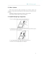
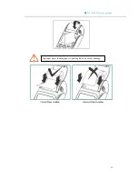
Page 41: ...erous locations are strictly prohibited When repairing no changes should be made to the component 5 3 Install Printing Paper Important 1 Press Cover Release Button to release and open the Printer Cove...

Page 42: ...NL 8510 POS user manual Improper paper loading leads to printing halt and causes damage 39...

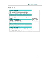
Page 43: ...Difficulty to read magnetic card Ensure the card is not demagnetized Ensure the magnetic bar is clean and tidy Use a cleaning card to clean the magnetic reader Difficulty to read IC card Ensure the sq...

Reviews: