background image


6


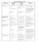
TROUBLE SHOOTING GUIDE 

SYMPTOM POSSIBLE 

CAUSE 

WHAT TO 

CHECK 

REMEDY 

 
CAN'T START BREW CYCLE


1. No water. 
 
 
2. No power. 
 
 
3. Warmer switch not on 
 
 
4. Brew start switch. 
 
 
5. Timer or timer harness. 


6. Solenoid valve. 


1. Incoming water lines & water shut  
    off valve. 
 
2. Fuse or circuit breaker. 
    Power cord and plug connections. 
 
3. Switch is on and lighted red, 

continuity 

 
4. Switch continuity. 
    (Normally closed.) 
 
5. Wire leads to solenoid and 
    white 3-pin connector. 
 
 
6. (A) Voltage at solenoid valve  
    terminals. Start a brew cycle and  
    check for 120 volts AC. 
    (B) If voltage is present at  
    terminals, check for water at line  
    pressure on the inlet side of  
    solenoid valve. 


1. Be sure water shut off is open. 
 
 
2. Replace or reset circuit protector 
 
 
3. If warmer switch does not make and  
    break contact, replace warmer switch. 
 
4. If brew start switch does not make and  
    break contact, replace brew start switch. 
 
5. Make sure these connections are tight. If  
    so, and all else checks out OK, replace  
    timer. 
 
6. (A) If voltage is not present at terminals,  
    refer to steps 2 through 5. 
 
    (B) If voltage is present at terminals and  
    water at line pressure is present on the  
    inlet side of the solenoid, but not present  
    on the outgoing side, replace solenoid. 


NO HOT WATER 

 
1. Tank heater. 


2. Hi-limit thermostat or main 
    thermostat. 

 
1.  Check the voltage at the tank  
    heater terminals. Voltage should be 
    as indicated on the serial tag (on 
    rear of brewer.) 


2. Check the voltage between the  

VIOLET/RED wire on the tank 
element and the  incoming terminal 
(VIOLET/BLACK) on tthe hi-limit 
thermostat, then the  outgoing 
terminal (VIOLET/BLACK) on  the 
hi-limit thermostat. 

 
1. (A) If correct voltage is present at the  
    tank heater terminals and water in tank is  
    not being heated, replace the tank heater. 
    (B) If voltage is not present  at the tank 
     heater terminals refer, to step 2. 
    (C) If incorrect voltage is present at the  
    tank heater terminals, check voltage at  
    outlet. 
 
2. (A) If voltage is present on the incoming 
     terminal of the hi-limit thermostat, but  
    not on the outgoing terminal, replace the  
     hi-limit thermostat. 
    (B) Check voltage  at the terminal blocks. 

If voltage is  not present check outlet or 
circuit breaker. 

    (C) If voltage is not present on the  
    incoming terminal of the hi-limit  
    thermostat, replace the main thermostat. 


DRIPPING 

 
1. Not siphoning properly. 


2. Solenoid valve not seating  
    properly. 


1. Water should flow freely from the 
    sprayhead. 
 
 
2. Solenoid valve assembly. 


1. (A) Clean sprayhead holes. 
    (B) Check tightness of sprayhead tube. 
    (C) See "DELIMING" , Page 5. 
 
2.  Be sure spring is in place and any  
    particles  are cleaned from valve seat. If 
    valve seat is  worn or mutilated, replace  
    solenoid valve. 


STEAMING OR SPITTING 
AROUND FUNNEL 

 
1. Main thermostat. 


2. High altitude. 

 
1. Thermostat points stuck or out of 
    calibration. 
 
 
2. Located above 5,000 feet. 

 
1. (A) Adjust  thermostat. 
    (B) Thermostat should be calibrated or 
    replaced. 
 
2. See "INSTALLATION 
    INSTRUCTIONS", Page 4.. 


WATER KEEPS RUNNING 

 
1. Solenoid valve. 
 
2. Start switch. 
 
 
3. Timer 


1. Refer to "DRIPPING", Step 1. 
 
2. Remove wires from switch and  
    check continuity. 
 
3. Solid state timers are not  
    repairable. If timer will not shut 
    off, replace timer. 


1. Refer to "DRIPPING", Step 1. 
 
2. If start switch does not make and break  
    contact, switch should be replaced. 
 
3. Replace timer. 

Summary of Contents for DB2A

Page 1: ... BREWER AUTOMATIC DB2A INSTALLATION OPERATION AND TROUBLESHOOTING MANUAL FOR DB2A AUTOMATIC BREWER WITH WARMERS POUR OVER Model DB2A 8 1 2 W x 18 D x 33 H 4700 Total Watts 23 3 AMPS 120 208 V Ship Wt approx 54 LB s Decanters Not Included ...

Page 2: ...2 ...

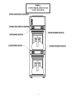
Page 3: ...DB2A CONTROL SWITCH LOCATIONS 3 ...

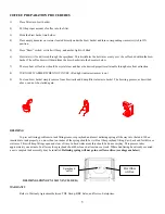
Page 4: ...n side of brewer 2 Adjust timer to deliver desired amount of water Timer is located behind front access panel To brew into a regular 64 oz decanter little adjustment should be needed Turn timer dial clockwise to increase volume of water and counter clockwise to decrease volume 3 Place the decanters under brew baskets turn on bottom two warmers and using brew switches brew three brew cycles or unti...

Page 5: ...To clean brew basket simply remove from brew rails and dump filter into waste basket The brewing process as described above can now be started again DELIMING To prevent liming problems in tank fittings remove sprayhead and insert deliming spring all the way into the tank When inserted into tank properly no more than ten inches of the spring should be visible at the sprayhead fitting Saw back and f...

Page 6: ...hi limit thermostat then the outgoing terminal VIOLET BLACK on the hi limit thermostat 1 A If correct voltage is present at the tank heater terminals and water in tank is not being heated replace the tank heater B If voltage is not present at the tank heater terminals refer to step 2 C If incorrect voltage is present at the tank heater terminals check voltage at outlet 2 A If voltage is present on...

Page 7: ...lter and coffee in brew basket 1 Insert correct filter 2 Refer to DRIPPING Step 1 3 Filter should be centered in brew basket and coffee bed should be level SOLENOID CHATTER OR HOWLING 1 Brewer connected to hot water line 2 Vibration 3 High water pressure 4 Water hammer 5 60 cycle vibration 1 Incoming water line 2 If brewer is on a metal stand or counter neither the bottom pan nor copper tubing to ...

Page 8: ...DB2A ACCESS PANEL COMPONENTS 8 ...

Page 9: ...REPLACEMENT PART DIAGRAM FRONT VIEW 9 ...

Page 10: ...55 54 1 33 32 3 47 4 34 REPLACEMENT PART DIAGRAM REAR VIEW 10 ...

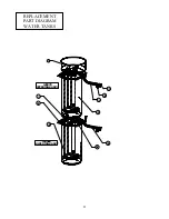
Page 11: ...41 22 5 27 58 39 42 36 23 74 120079 UPPER TANK ASS Y 120069 LOWER TANK ASS Y REPLACEMENT PART DIAGRAM WATER TANKS 11 ...

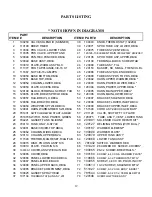
Page 12: ...098 BRACKET LOWER INLET DB3A 18 120059 WRAPPER SPTWLD DB3A 55 120099 BRACKET UPPER INLET DB3A 19 120091 HARN WARM TIMER SWI DB3A 56 151590 CORD ASY 240V 30A CM BAR 20 781431 SWITCH BREWER START AMBER 57 201128 VALVE SHUTOFF 1 4 FLARE 21 781870 SWITCH TANK POWER GREEN 58 120075 TUBE ASS Y VENT LOWER TANK 22 704221 GASKET TANK SILICONE 59 201991 SOLENOID VALVE REPAIR KIT 23 704119 TANK ONLY K STYLE ...

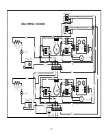
Page 13: ...NG THERMOSTAT VIO WARMER WH BK WH WH WH WH WH BK RD BK RD FILL SOLENOID FILL SOLENOID TIMER TIMER 5 4 2 1 6 6 BK YEL BK YEL VIO VIO VIO RD RD RD VIO BK YEL BK BK VIO VIO RD VIO RD VIO RD WH L1 L2 N E L1 BK VIO BK BK VIO GREY BK WH VIO RD BK BK BK BK YEL BK VIO VIO BK BK VIO BK VIO BK VIO BK BK BL VIO BK BK BK UPPER ELEMENT MIDDLE WARMER LOWER WARMER LOWER LOWER BREW UPPER BREW LOWER ELEMENT BK RED...

Reviews: