New Leader L4000G4 Manual Download Page 9

- 10 -

www.NewLeader.com

(800) 363-1771

313967-I

SPREAD PATTERN

Header

Spread Pattern

Determining Driving Centers

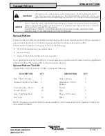
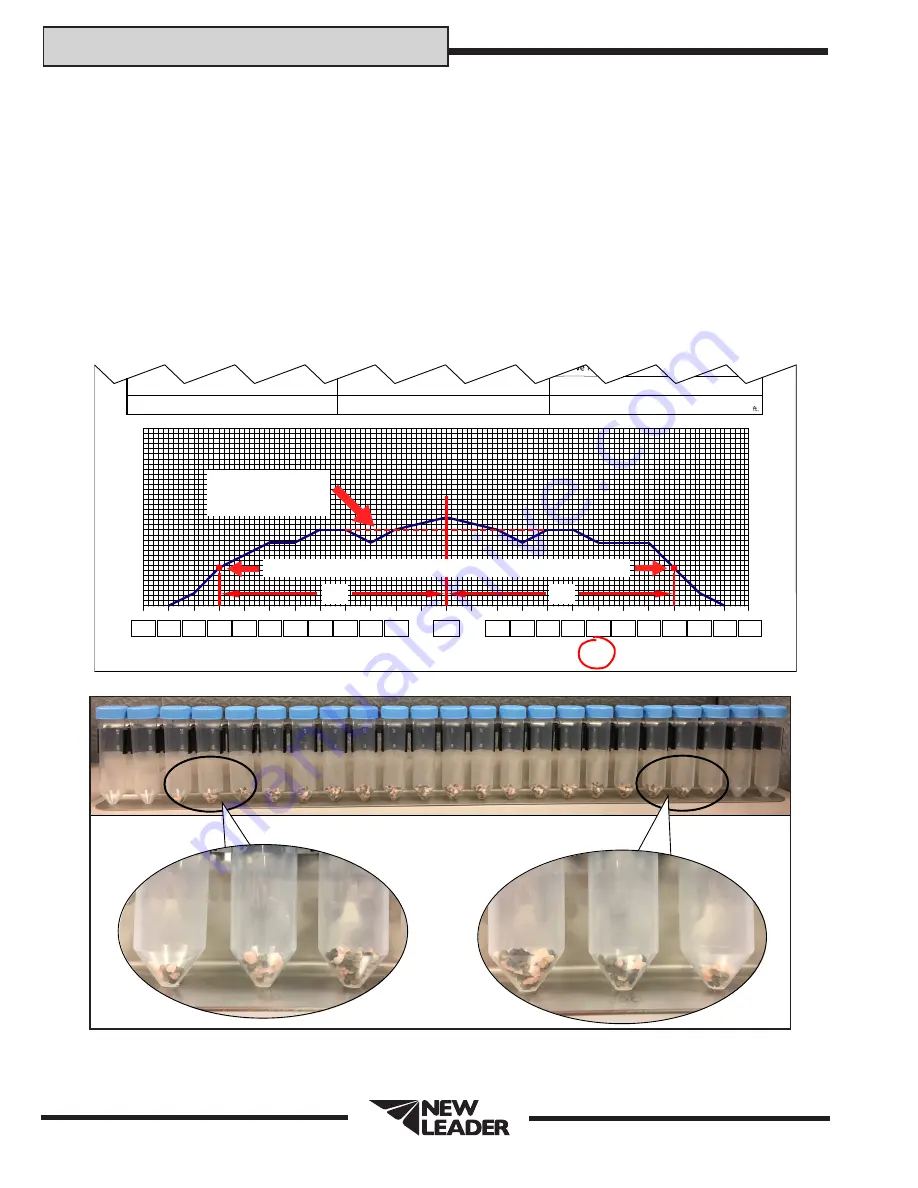
Once an acceptable pattern is obtained, as shown in Figure 5, driving centers can be determined. To 

determine optimum driving centers (effective swath width), determine the average amount of material 

in the center of the pattern. Figure 8 shows an example data sheet recorded from the profile shown in 

Figure 9. Based on the example, the  average amount of material in the center of the pattern is 3.0, as 

indicated with the red dotted line.

Next, locate the points on both the left and right side of the pattern where the amount of material is 

half the average amount at the center of the pattern. In the example shown in Figure 8, these points are 

located 45’ to the left of center, and 45’ to the right of center. The distance between these two points 

(90’) represents the driving centers to use.

NOTE: Once the effective swath width has been established, a change in the controller may be required.

313964-A

Temperature:

°F

lbs/acre

Spinner Speed:                                                                   

RPM

Controller Vehicle Speed:

MPH

Controller Swath Width:

10’

15’

20’

25’

30’

35’

40’

45’

50’

55’

-0-

10’

15’

20’

25’

30’

35’

40’

45’

50’

55’

1

2

3

4

5

6

7

1

2

3

4

5

6

7

60’

60’

3.5

3.0

3.0

3.03.0

3.0

3.0

2.5

2.5

2.5 2.5 2.5 1.50.5

2.5 2.5

2.0

1.5

0.5

ACCEPTABLE PATTERN

Average amount of 

material in the center

of the pattern = 3

EFFECTIVE SWATH WIDTH: 45’+ 45’ = 90’

45’

45’

Points where material is half of the center of the pattern = 1.5

Figure 8 - Effective Swath Width

Figure 9 

80’

80’

90’

90’

100’

100’

Summary of Contents for L4000G4

Page 1: ...s 7 Measure the depth of material on the end of the conveyor to verify the constant number feedgate height information entered into the controller Adjust feedgate height or recalibrate feedgate as necessary 8 Verify that all other product settings entered into the controller are correct 9 Select the correct bin in the controller for the first bin to be tested Enter the anticipated weight of produc...

Page 2: ... 2 NOTE If desired a material calibration kit is available to aid in measuring product quality Contact your local dealer for details WARNING Use great caution while working around the spreader Contact with spinners and other moving parts is very dangerous Do not adjust while machinery is moving wear eye protection and avoid discharge from spinners Do not ride on moving spreader NOTICE Spinner asse...

Page 3: ...n The spreader to be tested must be in good mechanical condition and properly adjusted Refer to operator s manual for details All damaged and worn parts must be replaced Spinner discs and fins must be free of any material build up rust or paint Fill the hopper with the material to be spread Run the material out to the end of the conveyor Set the feedgate and the in cab controller to deliver the re...

Page 4: ...ty Ground Speed mph Rate lbs Feedgate in Spinner Frame Setting Spinner RPM Lime 90 11 1000 5000 6 5 600 2000 8000 12 5 600 Urea 46 18 110 2 5 4 800 225 2 5 3 5 800 450 2 5 2 5 800 Corn Blend 53 18 125 2 5 3 5 800 250 2 5 2 5 800 500 2 5 0 7 800 All other fertilizer types and blends 64 18 150 2 5 3 5 800 300 2 5 2 5 800 600 2 5 1 2 800 15 mph when using high performance HP hydraulics ...

Page 5: ...67 90 Straight 41 5 10am Figure 1 Select an area for testing measuring at least 120 feet x 200 feet 37 m x 61 m and with a slope of less than two degrees All testing should be done when the wind velocity is less than 5 MPH 8 05 km If wind is present testing must be done with spreader traveling parallel within 15 degrees to the wind direction Do not allow loaded spreader to sit for more than one ho...

Page 6: ...5 0 8m 100 100 75 75 20 30 40 50 60 70 80 90 100 110 20 30 40 50 60 70 80 90 100 110 0 120 120 60 60 Figure 2 Four Wheeled Vehicles Three Wheeled Vehicles For three wheeled application vehicles straddling the center tray is not possible Place the center collection tray beneath the vehicle just behind the front tire when the spreader is in position at the beginning of the course See Figure 3 Engage...

Page 7: ...x on the data sheet under the corresponding tray position and graph the spread pattern profile See Figure 4 313964 A Temperature F lbs acre Spinner Speed RPM Controller Vehicle Speed MPH Controller Swath Width 10 15 20 25 30 35 40 45 50 55 0 10 15 20 25 30 35 40 45 50 55 1 2 3 4 5 6 7 1 2 3 4 5 6 7 60 60 3 5 3 0 3 0 3 03 0 3 0 3 0 2 5 2 5 2 5 2 5 2 5 1 50 5 2 5 2 5 2 0 1 5 0 5 Figure 4 Looking at ...

Page 8: ... Move the spinner rearward away from conveyor Light Outside Vehicle s Tire Tracks RATE ACRE 1 Check spinner fins for material buildup rust or paint 2 Increase spinner RPM 3 Move spinner fins to 2 3 2 3 positions See Figure below Pattern Off Center RATE ACRE 1 Check to see feedgate is level and free of caked material 2 Make sure hillside divider spinner assembly and material divider are mounted squ...

Page 9: ...the average amount at the center of the pattern In the example shown in Figure 8 these points are located 45 to the left of center and 45 to the right of center The distance between these two points 90 represents the driving centers to use NOTE Once the effective swath width has been established a change in the controller may be required 313964 A Temperature F lbs acre Spinner Speed RPM Controller...

Page 10: ...er the center of the trays down the AB line 5 Drive through the row of trays and switch back once again driving past the trays on the opposite side at an equal distance from the AB line as the first pass R20 R30 R40 R50 R60 R70 R80 R90 R100 R110 L20 L30 L40 L50 L60 L70 L80 L90 L100 L110 0 75 11 3m 75 11 3m OPTIMUM DRIVING CENTER EFFECTIVE SWATH WIDTH OPTIMUM DRIVING CENTER EFFECTIVE SWATH WIDTH AB...

Reviews: