


- 7 -
SPREAD PATTERN
www.NewLeader.com
(800) 363-1771
313967-I
Header
Spread Pattern
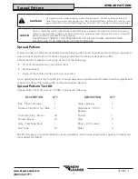
Four-Wheeled Vehicles
For four-wheeled application vehicles, position the
spreader at the beginning of the course so that the
vehicle will straddle the center collection tray. See Figure
2.
Engage spinners before navigating the course. As the
vehicle approaches the flag positioned 75’ before the
row of collection trays, engage the conveyor(s). Do not
shut the conveyor(s) off until the vehicle approaches the
second flag.
Drive spreader completely through course at normal
operating speeds.
10’ (1.5m)
20’ (3m)
5’ (0.8m)
100’
100’
75’
75’
20 30 40 50 60 70 80 90 100 110
20
30
40
50
60
70
80
90
100
110
0
120
120
60’
60’
Figure 2 – Four-Wheeled Vehicles
Three-Wheeled Vehicles
For three-wheeled application vehicles, straddling the
center tray is not possible. Place the center collection tray
beneath the vehicle just behind the front tire when the
spreader is in position at the beginning of the course. See
Figure 3.
Engage both the spinners and conveyor(s) before
navigating the course. Do not shut the conveyor(s) off
until the vehicle approaches the second flag.
Drive spreader completely through course at normal
operating speeds.
0
10’ (1.5m)
20’ (3m)
5’ (0.8m)
100’
75’
CENTER PAN
BEHIND
FRONT TIRE
75’
20 30 40 50 60 70 80 90 100 110
20
30
40
50
60
70
80
90
100
110
120
120
60’
60’
Figure 3 – Three-Wheeled Vehicles


