background image

iii

TABLE OF CONTENTS

Pages listed are a table of contents for that section

Section  -  Title  . . . . . . . . . . . . . . . . . . . . . . . . . . .   Page

1


- GENERAL INFORMATION

. . . . . . . . . . . . . .   1-1

General Service Information
Important Information
Service Tools
Safety
Units of Measure
Bolt Torque Information
Machine Specifications
Paint Touch-up Procedure

2


- ADJUSTMENTS

. . . . . . . . . . . . . . . . . . . . . . .   2-1

Air Drill Leveling 
Floating Hoe/Shank Adjustments
Sweep Pitch Adjustments

3


- MECHANICAL SERVICE

. . . . . . . . . . . . . . . .   3-1

Troubleshooting Tables
Servicing Safety Precautions
General Operating Information 
Grease Locations
Maintenance
Tire Pressures
Tire Pressures and hub and Spindle Details
Wheel Bolt Torque
Heavy Caster Assembly
Light Caster Assembly
Caster Hub and Spindle Maintenance
Walking Beam Replacement
Wing Dual Caster Option
Dual Wing Caster Clamp
Auxiliary Tow Hitch
Caster Transport Lock Installation
Pin Guides
Depth Control Service
Walking Beam Carrier Spool Replacement

4


- HYDRAULICS

. . . . . . . . . . . . . . . . . . . . . . . . .   4-1

Hydraulics
Replace Seals in Cylinders
Hydraulic Cylinders
Depth Control
Wing Lift Hydraulics

5


- ELECTRICAL

. . . . . . . . . . . . . . . . . . . . . . . . . .   5-1

Connector Service Kit
Remote Switch Installation

6


- TRIPS, OPENERS, AND PRESS WHEEL 

SERVICE

  . . . . . . . . . . . . . . . . . . . . . . . . . . . . .  6-1

Service of Openers
Service Guide for Offset Shank Locations
Press Wheels and Shanks
Ground Openers and Seed Boots
Troubleshooting Tables
Trip Compressor Tool Kit
Tension Link Kit - 550 Pound Trip
Adjustment of Trip Assemblies
Trip/Shank Shim Installation
Heavy Duty Bearing Kits
Press Wheel Removal
Packer Wheel Rest Assembly
Shank Spacing and Trip Release Pressure
Trip Assemblies
Sweep Pitch Adjustment
Trip Torque Specifications

7


- AIR SYSTEM

  . . . . . . . . . . . . . . . . . . . . . . . . . .  7-1

Troubleshooting Tables
Hoses
Theory of Operation - Air System
Determining Adequate Carrying Velocities
Header Assemblies
Hose Holder Brackets and Distribution Clamps

8


- ENDMARKER SERVICE

  . . . . . . . . . . . . . . . .  8-1

Endmarkers
Endmarker Replacement
Endmarker Hydraulics

INDEX

Find manuals at https://best-manuals.com

Summary of Contents for flexicoil 5000 AD.A

Page 1: ...5000 Air Drill Models AD A and AD B DR 015V2 1 05 Service Manual ...

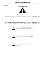
Page 2: ... second panel indicates the appropriate avoidance of the hazard z Background color is YELLOW z Prohibition symbols such as and if used are RED DR 015V2 Issued January 2005 THIS SAFETY ALERT SYMBOL INDICATES IMPORTANT SAFETY MESSAGES IN THIS MANUAL WHEN YOU SEE THIS SYMBOL CAREFULLY READ THE MESSAGE THAT FOLLOWS AND BE ALERT TO THE POSSIBILITY OF DEATH OR SERIOUS INJURY M171C STOP WARNING IMPROPER ...

Page 3: ...28 Saskatoon Saskatchewan Canada S7K 3S5 Internet Website http www flexicoil com The content of this book was based on the most current information available as of the date of copyright It is the policy of CNH Canada Ltd to improve and develop our products continuously We reserve the right to make changes or add improvements at any time without incurring anyobligation to make such changes on machi...

Page 4: ...This Page is Left Blank Find manuals at https best manuals com ...

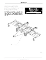
Page 5: ... machine The plate looks like the sample with a number stamped on For easy reference locate the plate at the location shown on the figure Record the number on this sheet When requiring repair parts take this number into your dealer This Serial Plate was used on machines manufactured to June 2004 Find manuals at https best manuals com ...

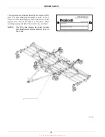
Page 6: ...or easy reference locate the PIN plate at the location shown on the figure below Record the number on this sheet When requiring repair parts take this number into your dealer NOTE This PIN plate replaces the Serial Number plate found on machines manufactured prior to June 2004 Find manuals at https best manuals com ...

Page 7: ... Control Service Walking Beam Carrier Spool Replacement 4 HYDRAULICS 4 1 Hydraulics Replace Seals in Cylinders Hydraulic Cylinders Depth Control Wing Lift Hydraulics 5 ELECTRICAL 5 1 Connector Service Kit Remote Switch Installation 6 TRIPS OPENERS AND PRESS WHEEL SERVICE 6 1 Service of Openers Service Guide for Offset Shank Locations Press Wheels and Shanks Ground Openers and Seed Boots Troublesho...

Page 8: ...iv This Page is Left Blank Find manuals at https best manuals com ...

Page 9: ... 10 Hydraulics and Hydraulic Leaks 1 10 Shields 1 11 Electrical 1 11 Tires 1 11 Safety During Transport 1 12 Safety Decals 1 12 Transport Lighting Brackets 1 14 Transport Lighting Electrical Assembly 1 18 UNITS OF MEASURE 1 22 Abbreviations 1 22 Conversion Chart 1 23 BOLT TORQUE INFORMATION 1 24 MACHINE SPECIFICATIONS 1 26 Implement Dimensions 1 26 Implement Weight 1 27 Other Specifications 1 30 P...

Page 10: ...SECTION 1 GENERAL INFORMATION page 1 2 This Page is Left Blank Find manuals at https best manuals com ...

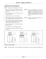
Page 11: ...ons sealant paste is recommended Be careful to prevent sealant from entering the hydraulic system 6 Apply a thread sealant to all female to male pipe thread connections 7 Do not allow tape to enter the hydraulic system 8 Do not use a thread sealant on ORB or swivel fitting connections NOTE If you are assembling or servicing the implement inside of a building ensure the door opening is large enough...

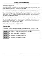
Page 12: ...tured or marketed by the manufacturer In any case no warranty is given or attributed on the product manufactured or marketed by the manufacturer in case of damages due to an anomalous behavior of parts and or components not approved by the manufacturer The information in this manual is up to date at the date of the publication It is the policy of the manufacturer to aim for continuous improvement ...

Page 13: ...THESE WORDS INDICATE THREE LEVELS OF POSSIBLE HAZARDS THEY ARE DESCRIBED BELOW Indicates an imminently hazardous situation that if not avoided will result in death or serious injury The color associated with Danger is RED Indicates a potentially hazardous situation that if not avoided could result in death or serious injury The color associated with Warning is ORANGE Indicates a potentially hazard...

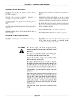
Page 14: ...AUTIONS BLOCKthewheelstopreventmovementwhenservicing BE SURE the press wheels are blocked and wing lock pins are in place before servicing or adjusting opener assemblies or working on the air drill The tractor engine should be stopped and the wheels blocked to prevent any movement during servicing Always be sure that the depth control safety lock is in place when servicing the air drill Always be ...

Page 15: ...s Hydraulic or mechanical failure may result in rapid or uncontrolled falling of the wings RAISE AND LOWER the wings only on level ground with the depth control fully raised PARK ON LEVEL GROUND and block adequately before servicing AVOID moving machines DO NOT sit or ride on moving implements Death or injury may result DISENGAGE POWER AND SHUT DOWN the tractor engine remove the key from the tract...

Page 16: ...ual thoroughly KEEP service area clean to prevent injury to service technicians and others DO NOT enter tight areas Be aware of pinch zones prior to commencing work BE CERTAIN machine is tagged out of order or work area is supervised BE CERTAIN all moving parts have stopped before servicing ...

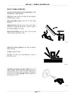
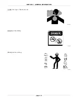
Page 17: ...SECTION 1 GENERAL INFORMATION page 1 9 0960039S 196150S 192078S AVOID toxic vapors Breathe clean air DO NOT permit smoking WEAR protective clothing ...

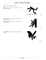
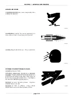
Page 18: ...eyes Use eye protection HYDRAULICS AND HYDRAULIC LEAKS AVOID high pressure fluids ESCAPING HYDRAULIC FLUID IS A SERIOUS HAZARD Escaping hydraulic fluid under pressure can penetrate the skin causing serious injury Relieve pressure before disconnecting the hydraulic lines Check tighten all connections BEFORE applying pressure BEWARE excessive hydraulic pressure Explosive structural failure can resul...

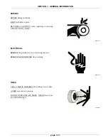
Page 19: ...lace BE EXTRA CAUTIOUS when repairing or servicing without protective shields ELECTRICAL REMOVE the ground wire to avoid arcing contacts REMOVE GROUND WIRE when welding TIRES USE A CAGE IF POSSIBLE when setting tires on rims AVOID excessive air pressure DO NOT OVER INFLATE TIRES NEVER lean over a tire while inflating it ...

Page 20: ...nsporting the air drill WATCH for power poles and overhead power lines ALWAYS lock the tractor drawbar when transporting the air drill ALWAYS park the air drill on level ground and block the wheels before unhooking from the towing vehicle NEVER subject the air drill to steep side grades while in transport position ALWAYS use the hitch jack supplied with the air drill when unhooking from the tracto...

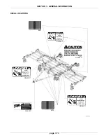
Page 21: ...SECTION 1 GENERAL INFORMATION page 1 13 GD 500 77 GD 500 77 GD 500 77 GD 500 77 GD 500 77 DECAL LOCATIONS 6026 6027 ...

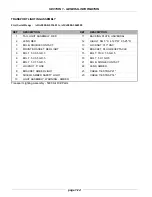
Page 22: ... 125 W X 5 25 D 3 BULB DOUBLE CONTACT 13 LOCKNUT 313 UNC 5 MOUNT BRACKET RED LIGHT 14 BRACKET PLUG RECEPTACLE 6 BOLT 5 X 3 5 GR 5 15 BOLT 313 X 1 5 GR 5 6 BOLT 5 X 5 5 GR 5 16 BOLT 5 X 1 GR 5 6 BOLT 5 X 7 5 GR 5 21 BULB SINGLE CONTACT 7 LOCKNUT 5 UNC 22 LENS AMBER 8 BRACKET AMBER LIGHT 23 CABLE TIE STRAP 21 9 SHIELD AMBER SAFETY LIGHT 23 CABLE TIE STRAP 14 10 LIGHT ASSEMBLY WARNING AMBER Transport...

Page 23: ...SECTION 1 GENERAL INFORMATION page 1 15 Transport Lighting Assembly First Serial Range ...

Page 24: ...C 23 BRACKET S M V SIGN 8 WASHER LOCK 5 YZD 24 PLATE BACKING UNIVERSAL 9 SIGN WARNING S M V 25 BRACKET AMBER LIGHT 10 U BOLT US 5 4 125W 5 25D 26 BRACKET PLUG RECEPTACLE 11 BOLT 25 X 75 UNC GR5 YZD 27 BRACKET MOUNT RED LIGHT DECAL 12 NUT LOCK 25 UNC 28 BRACKET AMBER LIGHT DECAL MOUNT 13 BOLT 313 X 1 UNC GR5 YZD 29 LIGHT ASSEMBLY WARNING AMBER 14 BOLT 5 X 1 UNC GR5 YZD 29 LIGHT AMBER 15 NUT LOCK 62...

Page 25: ...SECTION 1 GENERAL INFORMATION page 1 17 Transport Lighting Assembly Second Serial Range ...

Page 26: ...G TILLAGE 8 CONTACT PIN ELECTRICAL CONNECTOR 2 ELECTRICAL PLUG 7 POLE 9 SEAL ELECTRICAL CONNECTOR 3 ELECTRICAL SOCKET 7 POLE 10 PLUG CAB ELECTRICAL CONNECTOR 4 LIGHT ASSEMBLY WARNING AMBER 11 CONTACT SOCKET ELECTRICAL CONNECTOR 5 LENS AMBER 12 TAIL LIGHT ASSEMBLY RED 6 BULB SINGLE CONTACT 13 LENS RED 7 PLUG CAB ELECTRICAL CONNECTOR 14 BULB DOUBLE CONTACT Safety Lighting Electrical Assembly 5000 Ai...

Page 27: ...SECTION 1 GENERAL INFORMATION page 1 19 ...

Page 28: ...LASTIC 2C PLUG 4 SOCKET CONTACT 14 16AWG BRASS TIN PLATED 5 SEAL ELECTRICAL CONNECTOR 6 CONNECTOR ELEC PLASTIC 3C PLUG 7 SOCKET CONTACT 18 20AWG BRASS TIN PLATED 8 SEAL CONNECTOR GREEN 9 CONNECTOR ELEC PLASTIC 6C PLUG 10 CONNECTOR ELEC LOCK 6C PLUG DT 11 SOCKET CONTACT 16 18AWG COPPER NICKEL PLATED 12 SOCKET CONTACT 14 16AWG COPPER NICKEL PLATED 13 CONNECTOR ELEC METAL 7C RECEPTACLE 14 COVER RUBBE...

Page 29: ...SECTION 1 GENERAL INFORMATION page 1 21 Safety Lighting Assembly Second Serial Range ...

Page 30: ...t ft3 Liters L Degrees Fahrenheit F Meters m or M Degrees Celsius C Miles per hour mph Feet ft Milliliters mL Fluid ounces oz Millimeters mm Gallons per minute gal m Newton Meters N m Gallons per acre gal ac Ounces oz Gallons gal Pound force inches lbf in Hectares ha Pound force feet lbf ft Horsepower hp Pounds per square inch PSI Inch in Pounds lbs Kilograms per hectare kg ha Pounds per acre lbs ...

Page 31: ...This as a preview PDF file from best manuals com Download full PDF manual at best manuals com ...

Reviews: