


ASSEMBLY
OM 0471MW-A
[18]
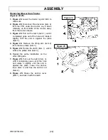
Figure 16
Figure 14
Figure 15
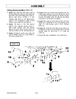
Deflectors Installation
(figures 14-15)
1. Figure 14:
Install the rubber deflector
(item 1) between the deflector support
(item 2) and the deflector reinforcement
(item 3). Secure with six 3/8"NC x 1 1/4"
carriage bolts (item 4), 3/8" x 1 1/2" OD
flat washers (item 5) and 3/8"NC nylon
insert locknuts (item 6).
2. Figure 14:
Attach the rubber deflector
(item 1) by installing first the 3/8"NC x 1
1/4" carriage bolt (item 4c), then the
3/8"NC x 1 1/4" carriage bolt (item 4a)
and finish with the four
3/8"NC x 1 1/4"
carriage
bolts (item 4b).
3. Figure 14:
Install two rubber bumpers
(item 7) with two 8-32 x 3/4" button head
cap screws (item 8), two #8 flat washer
and two 8-32 nylon insert locknuts (item
9).
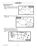
4. Figure 15:
Install the deflector assembly
(item 2) between the supports (item 3)
welded on the mower frame.
5. Figure 15:
Insert the ø7/16" x 9 13/16" lg
deflector pivot pin (item 1) through the
support welded to the frame (item 3) and
the deflector assembly (item 2), and a
torsion spring (item 4). The longest spring
rod must go on the deflector assembly
and the shortest one in the notch on the
support welded on the frame (item 3).
6. Figure 15:
Install a 7/16" flat washer
(item 5) at each end of the pin (item 1)
and secure with two circle cotters
(item 6).
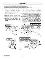
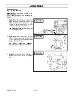
Driveline Installation to Mower
Figure 16:
Insert two
5/16” x 1 3/4" hex bolt
(item 1), lockwasher (item 2) and nylon insert
locknut (item 3) into the two side holes of the
driveline clamp yoke (item 4).Make sure to
install the bolts in opposite direction like
illustrated.
Do not tighten.
Attach the
driveline clamp yoke (item 1) to the gearbox
shaft (item 4) and secure with a 5/16" x 2"
hex bolt (item 5) and a 5/16" nylon insert
locknut (item 6). Tighten both hex bolts (item
1) and tighten the center hex bolt (item 5).
Summary of Contents for 266WMM
Page 9: ...GENERAL SAFETY INFORMATION OM 0471MW A 7 ...
Page 10: ...GENERAL SAFETY INFORMATION OM 0471MW A 8 1 Safety stand 2 Secure point for safety stand ...
Page 12: ...SAFETY LABELS OM 0471MW A 10 Replace immediately if damaged ...
Page 37: ...PARTS OM 0471MW A 35 UPPER PART OF MOWER FRAME ...
Page 39: ...PARTS OM 0471MW A 37 FRONT HITCH COMPONENTS ...
Page 41: ...PARTS OM 0471MW A 39 REAR HITCH COMPONENTS ...
Page 43: ...PARTS OM 0471MW A 41 DRIVE SYSTEM ...
Page 50: ......
Page 51: ... ...


