


15
6-2.
Wiring and Connection (Continued)
Typical Connection Procedure
(1)
Prepare a power supply that can provide 24 V.
(Do not turn on the power supply before wiring the main unit.)
(2)
Loosen the hexagon socket bolts on the four corners of the main unit using the
provided hexagon wrench with a nominal diameter of 4 mm, and open the casing
cover of the main unit.
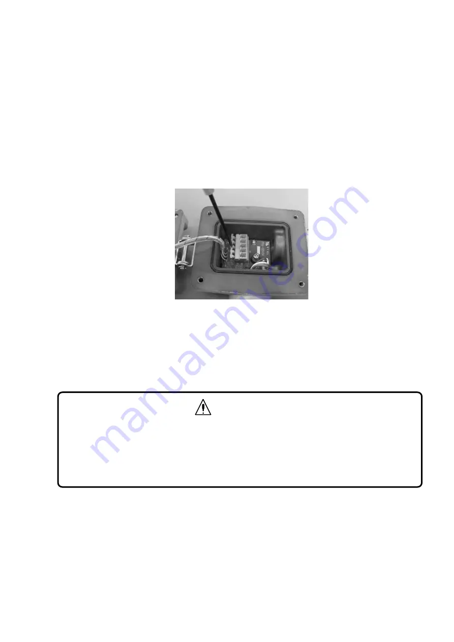
(3)
Press the lever of the terminal block with a flat-blade screwdriver.
(4)
The clamp will open. Insert the lead wire.
(5)
Connect the positive side of the power supply to the 24 V+ terminal.
(6)
Connect the negative side of the power supply to the GND terminal.
(7)
The lead wire will be automatically secured when the screwdriver is lifted.
(8)
Check that the power supply cords are securely connected to the terminals. This
completes the power supply preparations.
(9)
Wire the analog signal and external contact terminals, if required.
(10)
Tighten the hexagon socket bolts (tightening torque: 0.8-2.4 N
⋅
m) on the four corners
of the main unit and close the casing cover of the main unit.
CAUTION
When lowering the lever of the terminal block, be careful not to allow the flat-blade
screwdriver to slip off of the lever. Otherwise, the flat-blade screwdriver may damage the
sensor unit code or circuit board.
When closing the casing cover, make sure that the power supply cord, harness, and O-ring
are not caught by the casing cover.


