12
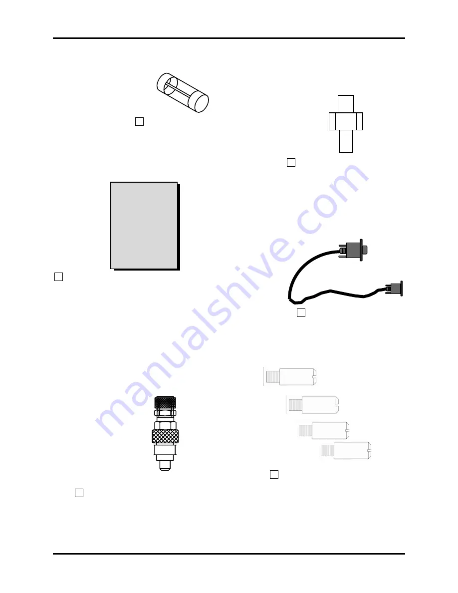
SPARE FUSE
GROUND POST SCREW
Anti–Foam
Module
User’s Guide
ANTI–FOAM MODULE USER’S GUIDE
ANTI–FOAM MODULE
INTERCONNECTING CABLE
(
15 PIN
)
4 SUPPORT PILLARS
CONDUCTANCE PROBE HEADPLATE FITTING
AF 2000 User’s Guide
Page 1: ...ERMANY New Brunswick Scientific UK Limited New Brunswick Scientific Benelux B V New Brunswick Scientific NV SA New Brunswick Scientific GMBH Edison House 163 Dixons Hill Road P O Box 6826 t Veldeke 1...
Page 2: ...rational Guidelines are not followed equipment damage can occur Please read the entire User s Guide before attempting to use the AF 2000 If Operational Guidelines are not followed equipment damage can...
Page 3: ...formation in this document without notice Updates to this information reflect our commitment to continuing product development and improvement Manual Conventions NOTE Notes contain important and usefu...
Page 4: ...his warranty is limited to repairing or replacing the instrument or part thereof which shall within 1 year after date of shipment prove to be defective after our examination This warranty does not ext...
Page 5: ...3 2 ENVIRONMENT 10 4 UNPACKING INSPECTION 11 4 1 UNPACKING THE EQUIPMENT 11 4 2 INSPECTION OF EQUIPMENT 11 5 ANTI FOAM MODULE FEATURES 13 6 GETTING STARTED 16 6 1 STACKING CONTROL MODULES 17 6 2 ANTI...
Page 6: ...E CURRENT VALUES 27 9 PREVENTIVE MAINTENANCE 27 9 1 CLEANING PROCEDURES 28 9 2 FUSE REPLACEMENT 28 10 TROUBLESHOOTING 30 11 REPLACEMENT PARTS AND ACCESSORY INFORMATION 31 11 1 REPLACEMENT PARTS DESCRI...
Page 7: ...7 This page intentionally blank New Brunswick Scientific Co Inc...
Page 8: ...he operation of a self contained feed pump that delivers anti foam agent and limits the agitation rate when high foam condition occur To operate the Anti Foam Module you must purchase a Conductance Pr...
Page 9: ...CTION VERIFICATION UNPACKING OF EQUIPMENT 2 1 INSPECTION OF BOXES After you have received your order from New Brunswick Scientific inspect the boxes carefully for any damage that may have occurred dur...
Page 10: ...back and the front of the Anti Foam Module for proper operation CAUTION When stacking additional Control Modules the pH 2000 should always be on the bottom When the pH 2000 is on the bottom and an aci...
Page 11: ...New Brunswick Scientific Service Department at 732 287 1200 800 237 2298 To properly unpack the AF 2000 perform the following steps 4 1 1 Open the top of the box 4 1 2 Remove the START UP KIT from the...
Page 12: ...RE FUSE GROUND POST SCREW Anti Foam Module User s Guide ANTI FOAM MODULE USER S GUIDE ANTI FOAM MODULE INTERCONNECTING CABLE 15 PIN 4 SUPPORT PILLARS CONDUCTANCE PROBE HEADPLATE FITTING AF 2000 User s...
Page 13: ...le CONDUCTANCE PROBE HEADPLATE FITTING Used on the VESSEL HEADPLATE Properly fits and seals the CONDUCTANCE PROBE into the VESSEL HEADPLATE ON OFF ROCKER POWER SWITCH Located on the lower left side of...
Page 14: ...ITY SENS ADJUSTMENT Located on the lower left side of the front panel Adjusts for the conductivity at which the and the CONDUCTANCE PROBE and the ANTI FOAM Module respond to the high foam probe being...
Page 15: ...oam Module Holds the working fuse for the Module Anti Foam Module Front Panel Foam Sensitivity SENS Adjustment Foam Probe Input On Off Rocker Power Switch NEW BRUNSWICK SCIENTIFIC Edison NJ U S A AF 2...
Page 16: ...16 Anti Foam Module Back Panel AF 2000 6 GETTING STARTED Fuse Receptacle 2 AMP T FUSE 15 Pin Power Control Connector AF 2000 User s Guide...
Page 17: ...LARS into the four holes on the top of the Anti Foam Module 6 1 3 Verify that the SUPPORT PILLARS are secure 6 1 4 Align any additional Control Module on top of the Anti Foam Module Verify that the ru...
Page 18: ...to OFF 6 2 2 Connect the flat female end of the ANTI FOAM MODULE INTERCONNECTING CABLE to the 15 PIN POWER CONTROL CONNECTOR on the back panel of Anti Foam Module 6 2 3 Tighten the thumbscrews on the...
Page 19: ...he Vessel HeadPlate See HeadPlate Illustrations 7 1 2 Verify that you screwed the CONDUCTANCE PROBE FITTING into the indicated 6 mm Port on the Vessel HeadPlate Conductance Probe Fitting Detail Back F...
Page 20: ...Electrode Spare Exhaust Foam Level Spare Exhaust Condenser Sample Harvest Ground Post Front NOTE When you use a FOAM PROBE and a LEVEL PROBE simultaneously use the FOAM LEVEL PORT and SPARE EXHAUST PO...
Page 21: ...e Cooling Coil 1 Cooling Coil 2 Front Spare Spare Exhaust Condenser 3 Way Inlet Sparger Spare Level Inoculation DO Electrode Sample Harvest Spare Exhaust Foam Ground Post Thermowell pH Electrode New B...
Page 22: ...adPlate Front Spare Cooling Coil 1 Cooling Coil 2 Spare Exhaust Exhaust C d 3 Way Inlet Foam Sparger Ground Post pH Electrode Spare Inoculation DO Electrode Sample Harvest Thermowell Spare Level Spare...
Page 23: ...ROBE to the desired liquid level and firmly secure the CONDUCTANCE PROBE by tightening the KNURLED RETAINING NUT with your fingers Do not tighten with a tool This will damage the Teflon coating on the...
Page 24: ...o CONDUCTANCE PROBES with the AF 2000 only one GROUND LEAD is connected to the Module 8 1 4 Connect the other end of the GROUND LEAD to a GROUND POST on the VESSEL HEADPLATE 8 2 SENSITIVITY ADJUSTMENT...
Page 25: ...ent in response to the conditions sensed by the CONDUCTANCE PROBE connected to the FOAM PROBE INPUT When foam contacts the sensing probe connected to the FOAM PROBE INPUT the AF 2000 begins to add inc...
Page 26: ...he AUTO mode the ANTI FOAM PUMP adds Anti foam agent in response to the conditions sensed by the CONDUCTANCE PROBE connected to the HIGH FOAM PROBE INPUT on the front panel of the AF 2000 When foam co...
Page 27: ...t modes until the light next to FOAM illuminates red New Brunswick Scientific Co Inc Bio Flo 2000 FERMENTOR ZERO CONT SET LEV FOAM SPAN DO TEMP AGIT NUTR HARV pH MODE SELECT FUNCTN SELECT D O CONTROL...
Page 28: ...the Anti Foam Module Perform the following steps to replace a fuse in the Anti Foam Module 9 2 1 Set the ON OFF ROCKER POWER SWITCH to OFF 9 2 2 Disconnect the ANTI FOAM MODULE INTERCONNECTING CABLE...
Page 29: ...ently press in and turn the FUSE SOCKET clockwise 9 2 10 Reconnect the ANTI FOAM MODULE INTERCONNECTING CABLE to the BioFlo 2000 Fermentor Fuse Replacement AF 2000 Fuse Socket 2 AMP T FUSE Fuse Notche...
Page 30: ...O SENS Adjustment is set too low Turn adjustment clockwise to increase sensitivity Conductance Probe connection is open Reconnect Conductance Probe Lead between AF 2000 and Conductance Probe GRND conn...
Page 31: ...rt Description NBS Part Number Fuse 20mm 2 Amp Slo Blow P0380 3261 Conductance Probe Vessel HeadPlate Fitting M1230 9489 Adapter 12 mm to 6 3 mm M1230 9413 Ground Post M1230 9411 Anti Foam Module Inte...
Page 32: ...2 VIO 5 WHI GRN GRY BLK FOAM MOD HI FOAM 14 8 GND PROBE FRONT PANEL ANTI FOAM HI FOAM FOAM 15 WAY D 15 10 VAC 18 VAC WHI PUMP BLU BLU 2 4 1 3 1 3 10 GRN YEL BLK RED 15 WAY D F1 BRN ORG YEL RED VIO 7 Y...
Page 33: ...ment 14 on off rocker power switch 13 power control 15 pin connector 15 support pillars 13 Fermentation Setup anti foam control 25 conductance probe cable connection 24 current values displaying 27 hi...
Page 34: ...cations 9 Support Pillars 13 T Troubleshooting 30 troubleshooting table 30 V Vessel HeadPlate 10 liter graphic 22 Vessel HeadPlate 2 liter graphic 20 Vessel HeadPlate 5 liter graphic 21 Vessel HeadPla...