Page 4 of 13
NPPA-TT-SD25 Instruction Manual
2. Replacement of Jack Pairs
Each individual jack pair can be exchanged or re-configured without fuss even while the unit is
“on air”. For replacement or re-configuration just remove the easy accessible module consisting
of two “Plug-in Units”.
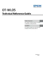
Module consisting of 2 Jack Pairs
Remove Front Panel by unscrewing the 3 black cross-recessed
screws (M3x8 Taptite), remove the two side-stops.
Push out the channel identification strips.
Pull one module out of the casing using the supplied
disassembling pliers