Netzer DF-150 User Manual Download Page 13

U

ser

 M

anUal

Page  13 of 16

DF-150 User Manual                      | Rev 1.0           

Netzer Precision Motion Sensors LTD Propriety

Preface

Safety

Product Overview

Unpacking    

Electrical 
Connection

Software 
Installation 

Mounting 
Verification

Calibration

Mechanical ICD

Mounting options

JUNE 2016

All specifications are subject to change without notice

Contents

DF-150  Rotary Electric Encoder

8. 

CALIBRATION

8.1  o

ffseT

  C

alibraTion


For optimal performance of the DF-150 Electric Encoder, the 
inevitable DC offset of the sine and cosine signals must be 
compensated over the operational sector.
After successfully completing the Mounting Verification 
procedure:
(

a)

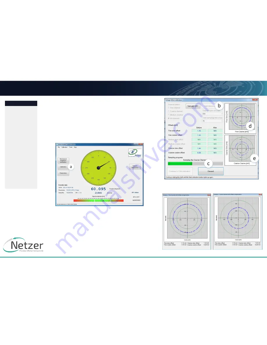
 Select [Calibration] on the main screen.


(

b

) Start the data acquisition while rotating the shaft.

The progress bar 

(c

) indicates the collection progress.

Rotate the axis consistently during data collection—covering 
the working sector of the application end to end—by default 
the procedure collects 500 points over 75 seconds. Rotation 
speed is not a parameter during data collection. Data collection 
indication shows for the fine/coarse channels, a clear “thin” 
circle appears in the center (

d

) (

e

) with some offset.

Offset compensated Fine / Corse Channel 

Summary of Contents for DF-150

Page 1: ...iew Unpacking Electrical Connection Software Installation Mounting Verification Calibration Mechanical ICD Mounting options JUNE 2016 All specifications are subject to change without notice Contents D...

Page 2: ...reface 3 1 1 Version 1 0 April 2016 3 1 2 Applicable documents 3 2 Safety 3 2 1 Safety issues 3 2 2 ESD notes 3 3 Product Overview 4 3 1 Overview 4 3 2 Installation flow chart 4 3 3 Encoder Mounting 5...

Page 3: ...otes Although the DF 150 Electric Encoder is insensitive to ESD and parasitic capacitive coupling from adjacent AC voltages we highly recommend to enable a discharge path with 20 k between the machine...

Page 4: ...sition Electric Encoder is a revolutionary position sensor originally developed for harsh environment critical applications Currently it performs in a broad range of applications including defense hom...

Page 5: ...DF 150 Rotary Electric Encoder 3 3 Encoder Mounting Typical encoder installation includes Encoder stator 1 Encoder stator mounting centralization holes 1a Encoder rotor 2 Encoder rotor shaft mounting...

Page 6: ...options JUNE 2016 All specifications are subject to change without notice Contents DF 150 Rotary Electric Encoder Encoder Stator Rotor relative position For proper performance the air gap should be 0...

Page 7: ...ptions JUNE 2016 All specifications are subject to change without notice Contents DF 150 Rotary Electric Encoder 4 UNPACKING 4 1 Standard Order The package of the standard DF 60 contains the encoder w...

Page 8: ...service mode provides access via USB to a PC running Netzer Encoder Explorer application on MS Windows 7 8 Communication is via Netzer Communication Protocol NCP over RS 422 using the same set of wire...

Page 9: ...ysis This chapter reviews the steps associated with installing the EEE software application 6 1 Minimum Requirements Operating system MS windows 7 32 64 bit Memory 4MB minimum Communication ports USB...

Page 10: ...alyzer under Tools 7 1 Starting the Encoder Explorer Make sure to complete the following tasks successfully Mechanical Mounting Electrical Connection Connecting Encoder for Calibration Encoder Explore...

Page 11: ...JUNE 2016 All specifications are subject to change without notice Contents DF 150 Rotary Electric Encoder e Select Start to initiate the data collection f Rotate the shaft for data collecting of the...

Page 12: ...2016 All specifications are subject to change without notice Contents DF 150 Rotary Electric Encoder In case the reading data blue dots are not evenly distributed on a thin circle you may experience n...

Page 13: ...he sine and cosine signals must be compensated over the operational sector After successfully completing the Mounting Verification procedure a Select Calibration on the main screen b Start the data ac...

Page 14: ...f the shaft in a limited angle defined by degrees in case of 10deg Free sampling modes define the number of calibration points in the total number of points in the text box The system displays the rec...

Page 15: ...DF 150 Rotary Electric Encoder 8 3 Setting the Encoder Zero Point The zero position can be defined anywhere in the working sector Rotate the shaft to the desired zero mechanical position Select Set Cu...

Page 16: ...ssy 1 2 DF 150_rotor_assy 1 D E F C 1 2 3 4 B A 3 2 1 5 C D 4 6 7 8 A B The information contaned in this drawing is the sole property ot Netzer Precision Motion Sensores Ltd Any reproduction in part o...

Reviews: