Network Technologies ST-C5KVM-1000S Installation And Operation Manual Download Page 16

NTI XTENDEX Extenders 


13

 
A momentary press of either the “+” (plus) or “-“ (minus) buttons button will make a minor change in the image.   If either button is 
pressed and held, the changes made will be gradual and continuous.   Ultimately, the image quality should improve to a 
satisfactory level.   Once the adjustment is made, it should not be necessary to change it again, as the new settings are stored in 
memory and become the default settings with each startup.   
 
If the image still lacks definition, configuration adjustments may need to be made to the attached video display equipment.   This is 
a problem most often seen in LCD displays.  Check the manual for the equipment having the poor display and look for an "auto-
adjust"  or "auto-configure"  feature.     Once this is done, you may need to repeat the Video Adjustment procedure described 
above to achieve the best image.    
 

Fine Video Quality Adjustment for KVM Models 

 
Models with keyboard support (ST-C5KVM-1000S, ST-C5KVM2A-1000S, ST-C5KVMRS-1000S, ST-C5KVM2ARS-1000S) are 
enabled with a Command Mode feature to perform the following: 


¾


fine adjustment of the general video quality  

¾


color skew adjustment  (alignment of red, green, and blue signals on the monitor)     

¾


update DDC information between the monitor and CPU 

¾


select the active microphone (between local and remote units) 


Most of the video quality adjustment is automatic at power ON,   but if some adjustment is necessary, this can be done using only 
the keyboard attached to the Remote Unit.  
 
To enter Command Mode;   
                                 1. press 

and hold

 the left  <

Shift> 

key


2.


press the right <

Shift>

 key.     

                                 3. Release both keys.    
    The three keyboard LEDs (NumLock, CapsLock, and ScrollLock) will blink to indicate entrance into Command Mode.  
 
Once in Command Mode, to fine tune the general video quality,  press the <

Left Arrow> 

or  <

Right Arrow>

 keys until the 

desired improvement in the display has been achieved.      
 

If a specific color appears to be skewed and is in need of fine adjustment, the user should select the color by pressing <

R>

, <

G>

 or 

<

B>

 respectively. The keyboard LEDs will identify the mode as indicated in the table below.   P

ress the < 

Left Arrow> 

or 

<

Right Arrow>

 keys until the desired improvement in the color alignment has been achieved.     


Tip:  To verify the need for and effect of color skew adjustment using a test pattern specifically designed for 
your display setting, browse the CD this manual was found on and click on the “test-pattern-nXm.pdf”  file 
that matches your current video resolution.  

 
To update DDC information, press <

D>

 and the Caps Lock and Scroll Lock LEDs will blink sequentially while the DDC data is 

transferred.  


Note:  It is recommended that the monitors connected to the Remote and Local units be of the same make and model.  


To toggle the active microphone between the Remote or Local unit,   press <

M>

.  The table below indicates how to determine 

which microphone is active after pressing <

M

>.      


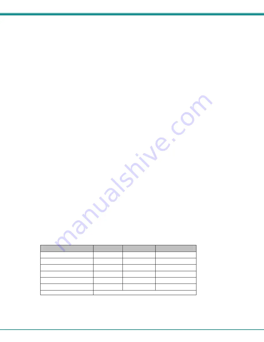
Keyboard  LED Indications 

Mode 

NUM LOCK 

CAPS LOCK 

SCROLL LOCK 

General Video Quality 

Blink 

Blink 

Blink 

Red Skew 

Blink 

Solid 

Solid 

Green Skew 

Solid 

Blink 

Solid 

Blue Skew 

Solid 

Solid 

Blink 

Local Microphone active 

Blink 

Blink 

Solid 

Remote Microphone active 

Solid 

Blink 

Blink 

DDC  

Sequentially blinking 

 
Press the<

A>

 key (while in Command Mode) to reset the fine tuning to default settings.   


Press the <

Esc>

 key to exit  Command Mode and return to normal operation.    All keyboard LEDs will return to current keyboard 

LED state.  


Summary of Contents for ST-C5KVM-1000S

Page 1: ...al XTENDEX Series ST C5V2ARS 1000S Video Audio and RS232 Extender ST C5KVM2ARS 1000S Keyboard Mouse Video Audio and RS232 Extender NETWORK TECHNOLOGIES INCORPORATED Tel 330 562 7070 Fax 330 562 1999 1...

Page 2: ...en consent of Network Technologies Inc 1275 Danner Drive Aurora Ohio 44202 CHANGES The material in this guide is for information only and is subject to change without notice Network Technologies Inc r...

Page 3: ...nformation 18 TABLE OF FIGURES Figure 1 Connect the Local Unit with VGA video and RS232 support to the CPU 6 Figure 2 Connect the Local Unit with audio support to the CPU 7 Figure 3 Connect the local...

Page 4: ...e user up to 1000 feet away Compatible with XGA VGA and SVGA systems Provides crisp and clear resolution up to 1920 x 1200 1000 feet see page 15 for more details Compatible with all NTI switches and s...

Page 5: ...cable s terminated with RJ45 connectors wired straight thru pin 1 to pin 1 etc see pg 16 for proper EIA TIA 568 B wiring method Cable s needed if Local Unit will be located further than 15 from the C...

Page 6: ...reen female 6 miniDIN for connecting the local user s mouse 7 Keyboard Connector purple female 6 miniDIN for connecting the local user s keyboard 8a Video Connector blue 15HD male for connecting to th...

Page 7: ...rt only 15 9VDC 1 0A connection jack for the AC adapter 16a Video Connector 15HD female for connecting the remote user s monitor 17 Buttons for fine video quality adjustment in models without keyboard...

Page 8: ...active at a time The user will select the active microphone via either push button or keyboard command PREPARATION FOR INSTALLATION Locations should be chosen for the monitors mice and keyboards that...

Page 9: ...the lime green 3 5mm stereo plug into the line out speaker or headphones jack on the back of the CPU See Fig 2 Connect the pink 3 5mm stereo plug to the line in or microphone jack on the back of the...

Page 10: ...VGA Multi Scan Touch screen Monitor PS 2 KEYBOARD PS 2 MOUSE 15HD Female Video Connector Front View of Local Unit ST C5KVMRS 1000S Local Unit Front and Rear View CAT5 Cable to Remote Unit Rear View o...

Page 11: ...speakers and microphone to XTENDEX Local Unit with audio support Note When two microphones are connected one at local and one at remote only one can be active at a time See mode charts on pages 12 an...

Page 12: ...RS232 cable from a touch screen monitor to the RJ45 port on the Remote Unit using the DB9M to RJ45 adapter and patch cable provided 5 If the Remote Unit has audio support connect the cable from the r...

Page 13: ...e Preparation for Installation instruction on page 3 Connect the CAT5 cable to the Cat 5 port on the Remote Unit See Fig 8 When properly inserted the CAT5 cable end should snap into place Note If an R...

Page 14: ...been made to them See Fig 9 Figure 9 Connect the AC adapter to the Remote Unit 3 Turn ON the CPU and Monitor They should each react as if they were directly connected to each other Note The yellow LED...

Page 15: ...n be used i e shielded vs unshielded cable and CAT5 vs CAT6 cable Models without keyboard support include a Mode button for the following functions fine adjustment of the general video quality color s...

Page 16: ...hree keyboard LEDs NumLock CapsLock and ScrollLock will blink to indicate entrance into Command Mode Once in Command Mode to fine tune the general video quality press the Left Arrow or Right Arrow key...

Page 17: ...f the desired level of image clarity cannot be achieved by making the adjustments described in this section consider the following possible adjustments that can be made Improve the quality of cable us...

Page 18: ...Models with Microphone Support Microphone Type Electret Audio Connector 3 5mm stereo jack pink to microphone 3 5mm stereo plug pink to CPU Input Impedance 10k Ohms Maximum Input Level 1 V unbalanced...

Page 19: ...e We will be happy to assist in any way we can Problem Cause Solution Remote or Local Unit green power LED does not illuminate Power supply is not connected or plugged in Make sure outlet is live and...

Page 20: ...both the Local and Remote extender units Otherwise it will be recognized and work only as a Microsoft Intellimouse Image is not displayed properly lacks definition Signal is being skewed by the CAT5...

Page 21: ...ebsite at http www networktechinc com for information regarding repairs and or returns A return authorization number is required for all repairs returns Note CAT5 connection cable used between NTI XTE...

Reviews: