


NTI XTENDEX Extenders
12
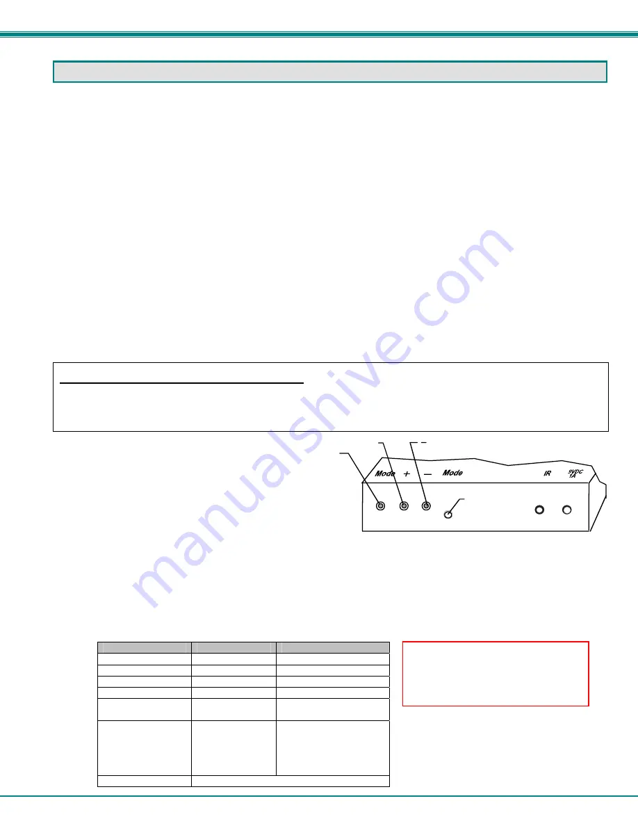
Mode button
+(Increase)
(Decrease)
Front View of ST-C5V-1000S
Mode LED
VIDEO ADJUSTMENTS
Automatic Video Quality Adjustment
Video quality is broken down into “general video quality” for brightness and sharpness of the images, and “color skew” for how the
colors align with each other on the monitor. All general video quality adjustment is done automatically while color skew is
adjusted manually as described in the following sections. Test patterns for color skew adjustment are provided on the CD (see
below). The automatic general video quality adjustment is calibrated for unshielded twisted pair cable. For shielded cable fine
adjustment may be necessary and this can be done from +/- push buttons on all models without a keyboard or from keyboard
keys using Command Mode on models that support a keyboard. Video Quality Adjustment settings are automatically stored in
the XTENDEX. Settings will be restored each time the XTENDEX is powered-ON.
Note: If the cable is changed after making fine video quality adjustments or color skew adjustments (below), the
XTENDEX will restore these settings to factory default and fine adjustments with the new cable may be necessary.
Fine Video Quality Adjustment for Video-Only Models
It is possible that on initial startup the image on the monitor will not be as crisp as the image normally is or the colors may not
appear as they normally would. The colors may also be skewed, or out of alignment as they appear on the monitor. This is due
to the frequency characteristics of the CAT5 cable and differences in cable types that can be used (i.e. shielded vs. unshielded
cable and CAT5 vs. CAT6 cable). Models without keyboard support include a “Mode” button for the following functions:
¾
fine adjustment of the general video quality
¾
color skew adjustment (alignment of red, green, and blue signals on the monitor)
¾
update DDC information between the monitor and CPU
¾
select the active microphone (between local and remote units)
Test Patterns for Color Skew Adjustment
To verify the need for and effect of color skew adjustment using a test pattern specifically designed for your
display setting, browse the CD this manual was found on and click on the “test-pattern-nXm.pdf” file that
matches your current video resolution. Follow the instructions below to make adjustments as needed.
Depending upon what mode the XTENDEX is in, the “+” (plus)
and “-“ (minus) buttons can be pressed to make the adjustment.
A “Mode” LED is provided to indicate what characteristic is being
changed.
Figure 10- Video Adjustment buttons
Note: The Local and Remote units must be connected and communicating in order for the mode button to function.
The chart below describes the video quality changes that can be made with the Mode button and the associated indication
provided by the Mode LED.
Mode Button
Action
LED Indication
Press + or – to effect:
At power ON
Dark (LED OFF)
General Video Quality
First Press
Red
Red Skew
Second Press
Green
Green Skew
Third Press
Orange
Blue Skew
Fourth Press
Green Flashing
DDC update
(press + or – to update)
Fifth Press
Red Flashing-
rapid or slow
Active microphone
Flash rapid= remote
Flash slow= local
(press + or – to toggle
which is active)
Sixth Press
Dark (LED OFF)- repeat cycle
Note: After pressing the Mode button,
if there is a pause in button activity
for 30 seconds or more, the feature
will return to a power-ON state with
the LED OFF.


