5
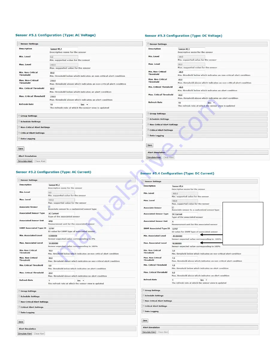
Click on the “Configure” button on any Status Page to display the Configuration page for any sensor.
Values shown here are for a 10Amp hall effect. A 30A DC voltage hall effect would use “-30” and “30” instead. (for example)
Page 1: ...0VAC and the other DC 60 to 60VDC Current measurements AC and DC up to 500A using hall effect transducers sold separately 2 and 4 position screw terminal connections Supports 18 24AWG CAT5 5e 6 cable up to 1 000 ft 305M not included Includes Mounting Ears CE certified and RoHS compliant Powered by E 2D 5D 16D Dimensions WxDxH in 6 2x2 3x1 6 Accuracy and range are transducer dependent sold separate...
Page 2: ...0VDC voltage source to be monitored to the Vin and earth ground connections using the removable terminal block 3 If current sensing is desired install a hall effect sensor to the AC or DC circuit to be monitored Then connect the supplied 4 wire cable to the sensor Connect the 4 wires at the end of the cable to the AC or DC CURRENT TRANSDUCER depending upon the type of circuit being sensed terminal...
Page 3: ...owing in that direction will be reported by the sensor as positive current flow When installing a hall effect sensor to a DC circuit you will want to install it oriented such that the arrow points in the direction you want represented as positive current flow on the status page for that sensor 3 Connect a 18 24AWG CAT5 5e 6 patch cable up to 1 000 feet long between the Cat x port on the E ACDCLM a...
Page 4: ...C Current The sensor is plugged into RJ45 Sensor port 5 in this example Click on the Sensor in the Description column or View under Action and display the status page for each sensor Below In order to better define the sensor on the Summary Page in SNMP traps or in an MIB browser click on the Edit link to open the sensor configuration page and configure the sensor ...
Page 5: ...k on the Configure button on any Status Page to display the Configuration page for any sensor Values shown here are for a 10Amp hall effect A 30A DC voltage hall effect would use 30 and 30 instead for example ...
Page 6: ...B file 2 locate the section titled extSensorType 3 assign a description and a number not already in use in the SYNTAX field to associate with it 4 enter the number for the newly defined extSensorType in the SNMP Custom Type ID box If the Type ID is left blank the value 0 will be assigned which will be reported in the browser and SNMP trap as type undefined TECHNICAL SPECIFICATIONS Description Spec...