background image

DA-HDSDI  


Rev. 4


DATE: 05 October 2007 


Network Electronics ASA, P.O.Box 1020, N-3204 Sandefjord, Norway. Tel.: +47 33 48 99 99 – Fax: +47 33 48 99 98 

E-mail: [email protected] – Web: http://www.network-electronics.com/ 
 
Technical specifications are subject to be changed without notice. 


5

2. Specifications 

 
Electrical Input 

Data rate NRZ: 


19.4 to 1485 Mbps 

Equalisation: 

    Automatic 


Cable equaliser and reclocker can be bypassed to 
support bitrates down to 1Mbps. 

Impedance: 

    75 

ohm 

Return 

loss: 

    >15dB 

1485MHz 

Signal 

level: 

    nom. 

800mV 


Apx. 200mV min. when equaliser switched to Bypass 

Connector: 

    BNC 

 
Electrical Output 

Number 

of 

outputs: 

   6 

Connector: 

    BNC 

Impedance: 

    75 

ohm 

Return loss:   


>15dB, acc. to ITU-R BT.1120-3 

Jitter: 

     max 

0.2UI 

Peak to peak signal level: 


0.8V 

±

 0.1V 

Signal 

polarity 

    3 

non 

inverting, 

3 inverting 


Features 

Re-clocking: 

    Automatic 

SD 

HD 

detection 

Automatic output slew rate adjustment according to  
SMPTE-259M / SMPTE 292M 
Selectable loop bandwidth  

Low: HD = 1.5MHz, SD = 500kHz 
High: HD = 3MHz, SD = 1MHz 

Supported clock rates:  


143, 177, 270, 360, 540 and 1485Mbps 

Input equalizer: 


Eq. bypass for non-video formats or low bit rates 


Electrical 

Power: 

     +5V 

DC 

3W 

Max. 

Control: 


Control system for access to setup and module status 
with BITE (Built-In Test Equipment) for use with GYDA 
Control System 

Supported standards


SMPTE: 

SMPTE292M, SMPTE259M, SMPTE297M, SMPTE305M, 
SMPTE310M 

DVB-ASI: EN50083-9 
AES: 

AES-3id (with EQ and RCL switched off) 

Summary of Contents for DA-HDSDI

Page 1: ...HD SDI Distribution Amplifier Network Electronics ASA Thor ya N 3204 Sandefjord Norway Phone 47 33 48 99 99 Fax 47 33 48 99 98 e mail support network electronics com www network electronics com E mail...

Page 2: ...evision history The latest version is always available in pdf format on our web site http www network electronics com Current revision of this document is the uppermost in the table below Revision Rep...

Page 3: ...l 4 2 Specifications 5 3 Format Configuration 6 3 1 Configuration Examples 7 4 Connector module 8 4 1 Mounting the connector module 8 5 Module status 9 5 1 GPI ALARM Module Status Outputs 9 5 2 Front...

Page 4: ...nd SD rates and automatically switch to correct output slew rate The re clocker supports the bit rates 143 177 270 360 540 and 1485Mbps For other rates the re clocker automatically switches to bypass...

Page 5: ...Number of outputs 6 Connector BNC Impedance 75 ohm Return loss 15dB acc to ITU R BT 1120 3 Jitter max 0 2UI Peak to peak signal level 0 8V 0 1V Signal polarity 3 non inverting 3 inverting Features Re...

Page 6: ...ting of equaliser when signal strength is to low Input mute 3 RCL Reclocker Bypass Reclocker ON Reclocker mode 4 EQ Cable equaliser Bypass Cable equaliser ON Equaliser mode 5 ASI SDI 177Mbps Reclocker...

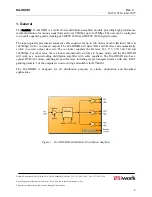
Page 7: ...ypical configurations for DA HDSDI Figure 3 Default HD SDI SDI and DVB ASI Figure 4 Transparent Mode with equalisation and no reclocking Figure 5 AES3id compatible and Transparent Mode without equalis...

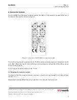
Page 8: ...NC and the electrical outputs are connected to the O1 to O6 BNC Please note that O2 O4 and O6 has an inverted signal so formats like DVB ASI can not use be used on these outputs Unused outputs should...

Page 9: ...oller is described in a separate user manual 5 1 GPI ALARM Module Status Outputs These outputs can be used for wiring up alarms for third party control systems The GPI outputs are open collector outpu...

Page 10: ...has 4 LED s each showing a status corresponding to the GPI pinning The position of the different LED s is shown in figure 8 Diode state Red LED Yellow LED Green LED No light Status Module is faulty Mo...

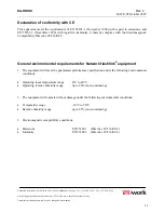
Page 11: ...y it thereby complies with the Electromagnetic Compatibility Directive 89 336 EEC General environmental requirements for Network flashlink equipment 1 The equipment will meet the guaranteed performanc...

Page 12: ...m Web http www network electronics com Technical specifications are subject to be changed without notice 12 Product Warranty The warranty terms and conditions for the product s covered by this manual...

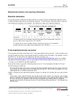
Page 13: ...period This is defined as the period of normal use before any hazardous material is released to the environment The guidance on how the EFUP is to be calculated is not finalised at the time of writin...

Page 14: ...network electronics com Please contact Network Electronics Customer Support for assistance with recycling if this site does not show the information you require Where it is not possible to return the...

Reviews: