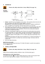
NetterVibration NTS 100/01 Operating Instructions Manual Download Page 7


Installation 


Observe the safety instructions in chap. Safety, from page 3 on. 


Maintenance unit 
 (NTS L: without mist lubricator) 


2  3/2-way valve 


3  NTS 


1. 

Notice: 

The NTS must lie completely on the surface. The mounting surface has to be flat 

(±0.1 mm flatness) and clean with no paint residues or burn-ins. 

Netter

Vibration

 recommends mounting the NTS on a weld-on console or a glueing con-

sole. For operation a 3/2-way valve (minimal valve function) has to be used. 

2. 

Mount the NTS on the console with one or four fastening screws (depending on the type) 
and suitable safety washers. If necessary, additionally use a medium-strength liquid 
safety agent to secure the screw connections. Observe the recommended values for 
screw sizes and tightening torques. 

3. 

Fasten the compressed air supply securely. Observe the recommended cross-sections 
for valves and hoses. For the air supply, use screw connections with integrated flat seal 
or liquid sealant. The air resistance increases with the hose length. The specified nomi-
nal diameters apply to hose lengths up to 3 m. Longer supply lines require larger cross-
sections. 
Discharge the escaping air through a hose if necessary (e. g. in dusty environments). To 
achieve full performance, the exhaust hose must have a larger nominal size than the 
supply hose. 

4. 

Mount the silencer/silencers. 


Synchronous operation


NTS can also be operated synchronously. For further information to synchronous operation 
contact 

Netter

Vibration


Start-up and operation 


Observe the safety instructions in chap. Safety, from page 3 on. 


Observe the permissible operating conditions in chap. Technical data, page 4. 


Starting pressure at low temperatures


At ambient temperatures 

 10 

°C higher starting pressures (≥ 2 bar) may be required. Start 

the NTS with a higher pressure of approx. 5 bar and then reduce to 2 bar. 

Standard 
installation 

Summary of Contents for NTS 100/01

Page 1: ...4 02 NTS 50 04 NTS 21 04 NTS 50 08 NTS 50 10 NTS 30 10 NTS 50 15 NTS 50 20 NTS 30 20 NTS 24 20 NTS 50 40 NTS 20 40 Use and storage Before installing the NTS read these instructions carefully It is the...

Page 2: ...of our knowledge into account No claims can be derived from the information illustrations and descrip tions in these operating instructions The manufacturer does not assume liability for damages resu...

Page 3: ...s well as fastening and housing screws can come loose due to vibration Falling parts lead to severe personal injuries Check the fastening and housing screws after one hour of operation and thereafter...

Page 4: ...the permissible ambient temperature according to Ch Technical data page 4 NOTICE Operation of the NTS with silencers is mandatory Silencers reduce the noise level and protect the NTS from contaminatio...

Page 5: ...ps minute 54 02 50 04 50 08 50 10 50 15 50 20 3 4 drops minute 21 04 30 10 30 20 50 40 5 7 drops minute 24 20 9 drops minute 20 40 15 drops minute Further technical data of the NTS can be found in the...

Page 6: ...housing and start spring 8 exception NTS 21 04 Version 2 with steel housing and start connection 7 NTS version 2 units can not start when installed horizontally due to the unfavourable position of the...

Page 7: ...cross sections for valves and hoses For the air supply use screw connections with integrated flat seal or liquid sealant The air resistance increases with the hose length The specified nomi nal diamet...

Page 8: ...ntervals 1 s it is possible that the NTS will not start immediately The reason for this is that the piston has not yet been pushed into the end posi tion by the spring NTS version 1 or by gravity NTS...

Page 9: ...re the NTS Exhaust air throttled too much Open the throttle valve further Clean silencer Thread of grommet is too long Check if the housing is deformed In case of deformed housing have the NTS checked...

Reviews: