NETGEAR HE102 - Wireless Access Point User Manual Download Page 5

Preliminary


Access Point User’s Guide   

 Page 5 


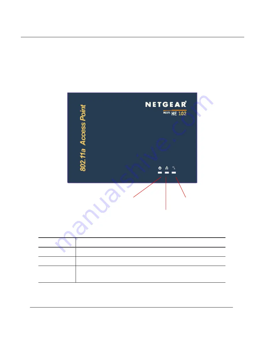
2  Getting to Know the Model HE102 Access Point 

2.1  Front View 

The Model HE102 Access Point (AP) has 3 LED’s, and a pair of side-mounted antennas 
that rotate 180

°

 for alternative reception positioning and compact packaging. 


Table 1 – LED Functionality 


LED 1 

Description 

Off 

No Power 

On 

Power On and Ready for Operation 

Blink 

Power On but Not Ready for Operation – at initial power on or reset, this 
indicates self-test or software loading; at other times, this indicates a system fault  


LED 1 (Power Status) 

LED 2 (Ethernet Link) 

LED 3 (Wireless Link) 

Summary of Contents for HE102 - Wireless Access Point

Page 1: ...Preliminary Access Point User s Guide Page 1 802 11a Wireless Access Point Model HE102 User s Guide Rev 1 2 11...

Page 2: ...harmful interference to radio or television reception with can be determined by turning the equipment of and on the user is encouraged to try to correct the interference by on or more of the following...

Page 3: ...GETTING TO KNOW THE MODEL HE102 ACCESS POINT 5 2 1 FRONT VIEW 5 2 2 REAR VIEW 6 3 AP NETWORK ATTACHMENT AND CONFIGURATION 8 3 1 AP NETWORK CONFIGURATION AND NETWORK BOOT 8 3 2 CONFIGURING THE AP THROU...

Page 4: ...istics setup configuration and usage 1 2 Features The Model HE102 Access Point is an IEEE 802 11a AP supporting up to 60 IEEE 802 11a station associations including the AP itself Rates of 6 to 54 Mbps...

Page 5: ...hat rotate 180 for alternative reception positioning and compact packaging Table 1 LED Functionality LED 1 Description Off No Power On Power On and Ready for Operation Blink Power On but Not Ready for...

Page 6: ...Link Activity blink rate is proportional to activity LED 3 Description Off Wireless Link Disabled Very Slow Blink Looking for Network Association Slow Blink Associated with Network but No Activity Fas...

Page 7: ...ctivity to a wired Ethernet LAN The Ethernet jack is wired for direct connection to a Ethernet hub or switch The restore to default push button is to allow the Access Point to be reset back to the fac...

Page 8: ...included 2 Plug in the 3 3 V power supply adapter provided by NETGEAR to the AP power supply connector Figure 1 Connection Between AP and Host PC At this point the Windows based HPC needs the followi...

Page 9: ...Preliminary Access Point User s Guide Page 9 3 Within the Local Area Connection Properties window choose Internet Protocol TCP IP and click Properties...

Page 10: ...ress for the Ethernet connection in the Internet Protocol TCP IP Properties window Click OK to continue and close Local Area Connection Properties Note that this IP address is used by the HPC to acces...

Page 11: ...owser 1 Launch a web browser Netscape Navigator or Internet Explorer are examples of commonly used web browsers from the Host PC or other PC on the same IP subnet as the AP and enter the IP address th...

Page 12: ...d IEEE Radio Channel that the stations STAs are associating in Infrastructure mode Click Apply to commit the changes At this time you can also change other settings Refer to Appendix A for detailed in...

Page 13: ...ontrol Transmit Power parameter This feature can be used to decrease the transmit power and therefore reduce the range of the radio In this operation mode more than one AP with the same channel freque...

Page 14: ...cy WEP for security purposes To set up WEP click WEP and the configuration screen appears Refer to Appendix A for a detailed explanation of the WEP configuration options Click Apply to save the settin...

Page 15: ......

Page 16: ...P as the URL address for example http 192 168 1 1 The web server home page contains several hyperlinks that provide viewing of the system information status of the AP and associated stations and confi...

Page 17: ...Preliminary Access Point User s Guide Page 17...

Page 18: ...rameters you must click Apply to save the changes The new configuration is not in effect until you reboot the AP Click Reboot to reboot the AP The web browser loses connectivity with the AP web server...

Page 19: ...Preliminary Access Point User s Guide Page 19...

Page 20: ...shared key can access to the network Yes Enable Yes No Allow 1 STA with matched MAC ID can access to the network 2 Any STAs with matched shared key are also allowed to access to the network Yes Enable...

Page 21: ...x 1 Only STA with MAC ID and or unique key matched to the setup in ACL can access to the network 2 The STAs with only shared key are blocked from accessing the network After entering or modifying the...

Page 22: ...ew the configuration of a unique key use the pull down menu to select the unique key ID select Read inside the Unique Key frame and then click Apply to view the unique key In this example unique key I...

Page 23: ...Preliminary Access Point User s Guide Page 23...

Page 24: ...s select Write enter the key changes select the appropriate key size select a unique key ID and click Apply Use the same procedure to add new unique keys Note that the unique key ID starts from 5 and...

Page 25: ...Preliminary Access Point User s Guide Page 25 To delete a unique key select Delete use the pull down menu to select the unique key ID that contains the unique key you want to delete and click Apply...

Page 26: ...Guide Page 26 To view the ACL list select Read inside the ACL frame enter the ACL ID to be viewed and click Apply In this example ACL ID 1 is selected and displayed and specifies that MAC address 00 3...

Page 27: ...Preliminary Access Point User s Guide Page 27 In this example ACL ID 3 is selected and displayed and specifies that MAC address 11 11 11 11 11 11 is allowed access with unique key 6...

Page 28: ...ter key ID if needed select either Deny or Allow and click Apply to save the changes In this example the new ACL entry has the MAC address 08 00 20 ac 37 51 using shared key 1 to allow access The next...

Page 29: ...Preliminary Access Point User s Guide Page 29...

Page 30: ...Preliminary Access Point User s Guide Page 30 To delete an ACL entry select Delete enter the ACL ID to be deleted and click Apply In this example ACL ID 2 is deleted...

Reviews: