


Chapter 1: Introduction
|
13
Managed Stackable Switches GSM7200PS and GSM7300S Series Hardware Installation Guide
•
SFP+ Adapter AX743
•
CX4 Adapter AX744
•
ProSafe 24-Gigabit Stackable Module AX742.
For more information, see
“Adapters and Modules Compatible with the High-Speed I/O
Module Bays”
on page 2-21.
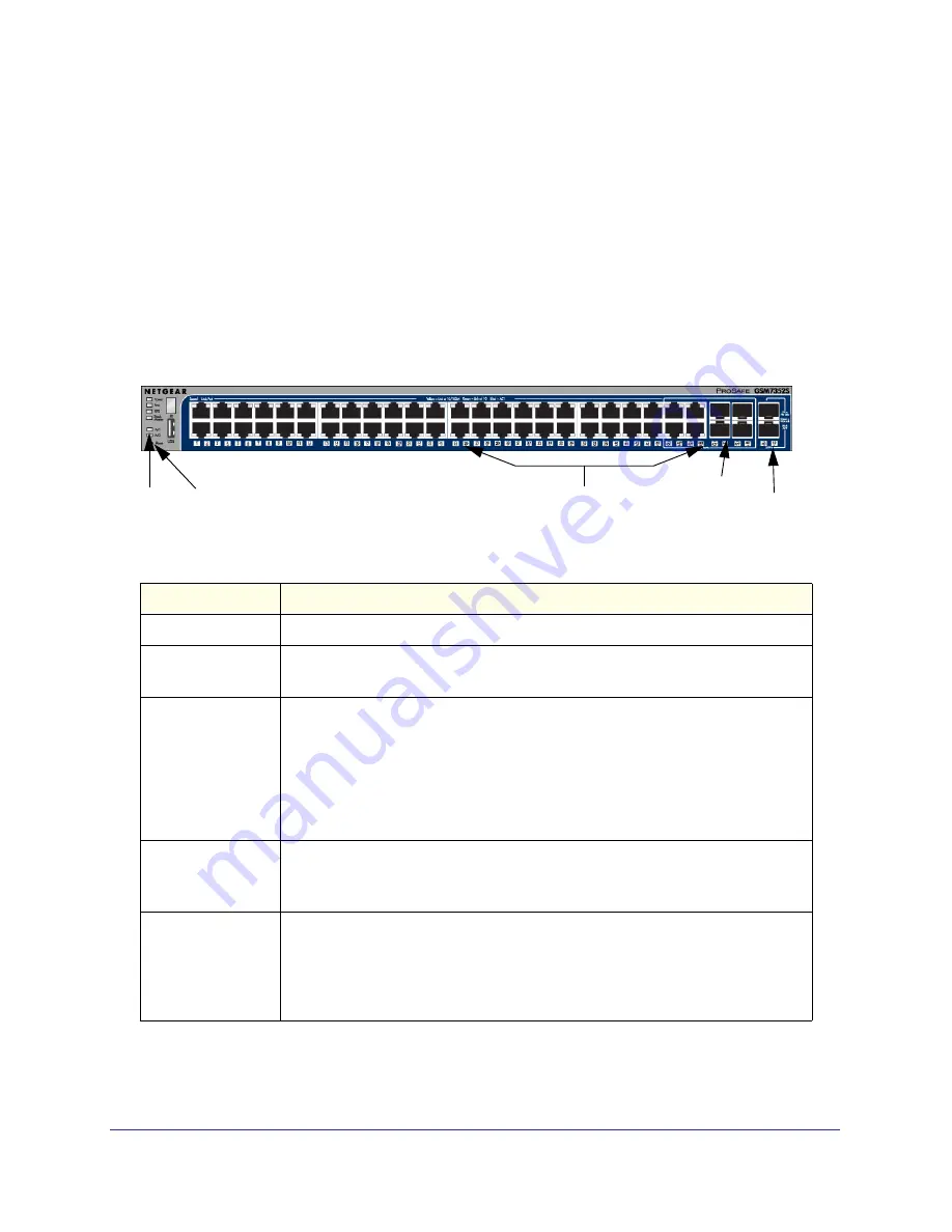
GSM7352S Front Panel and LEDs
The following figure shows the front panel of the GSM7352S. The front panel contains LEDs,
a Reset button, a USB port, RJ-45 jacks, copper/fiber combo ports, and 10G SFP+ ports.
Figure 1-7 GSM7352S Front Panel
Table 1-6. GSM7352S LED Description
LEDs
Description
ID
This is the stack member ID (1–8) that the software assigns to the switch.
Master
•
Green
: The switch is a master unit in a stack of GSM7300S series switches.
•
Off
: The switch acts as a slave unit in a stack of GSM7300S series switches.
RPS
(redundant power
supply)
•
Solid green
: The redundant power supply is connected (and using the power
module’s power).
•
Solid yellow:
The power module’s has failed or been disconnected, but the
redundant power supply is providing power to the switch.
•
Blinking yellow
: The redundant power supply unit is present but the power has
failed.
•
Off:
The redundant power supply is disconnected or not present.
Fan
•
Solid green
: Fan operating normally.
•
Solid yellow:
Fan has failed
•
Off:
No fan detected.
PWR (Power)
•
Solid green:
Power module is present and is supplies power to the the switch
and is operating normally.
•
Solid yellow
: System is in boot-up stage.
•
Blinking yellow
: POS/ CPU system has failed.
•
Off
: Power is disconnected.
RJ-45 jacks
LEDs
Reset button
SFP+ Ports
Combo Ports


