background image

Installation Guide for the Model SW108 Ethernet Switch

5-2

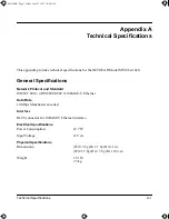
Troubleshooting

Port connection 
not functioning

Link LED off or 
intermittent

After the cabling has been installed, if the Link LED is not lit on 
an active port, check the attached device and make sure that it 
is powered on and there is a proper UTP connection at that 
end. Also make sure that the proper cable is installed, and 
check for miswired cable pairs or loose connectors. 
If the Link LED is on intermittently, check the port termination at 
both the switch and device ends. Check the crimp on the RJ-45 
connectors. 
Check that the length of the UTP cable from the switch to the 
device does not exceed 328 feet (100 meters). Using cable test 
equipment, check that the cable meets the specifications as 
required by the 10BASE-T standard. Refer to Chapter C, 
“Cabling Guidelines,” for information on cable specifications.
Make sure the network adapter card installed in the PC is in 
working condition. 
Make sure that there is power to both the switch and the 
connected PC.

Problems with port 8 
on the Model SW108 
switch

Link LED off

Check the Normal/Uplink push button on the front panel. 
If you are using a straight-through cable connected to a PC or 
other MDI-wired device, make sure the Normal/Uplink push 
button is set in the Normal position.
If you are using a straight-through cable connected to a router 
or another switch, make sure the Normal/Uplink push button is 
set in the Uplink position.
Try the alternate position of the Normal/Uplink push button to 
turn the Link LED on.
Refer to Chapter C, “Cabling Guidelines,” for cable information.

Table 5-1.

Troubleshooting (continued)

Symptom

Activity

Check

SW108.BK  Page 2  Friday, June 27, 1997  10:48 AM

Summary of Contents for ETHERNET SWITCH SW108

Page 1: ...SW108NA 0 June 1997 NETGEAR Inc A Bay Networks Company 48015 Warm Springs Blvd Fremont CA 94539 USA Installation Guide for the Model SW108 Ethernet Switch SW108 BK Page i Friday June 27 1997 10 48 AM...

Page 2: ...interference to radio communications Operation of this equipment in a residential area is likely to cause harmful interference in which case users will be required to take whatever measures may be ne...

Page 3: ...Customer Support For assistance with installing and configuring your NETGEAR system or with post installation questions or problems contact your point of purchase representative To contact customer su...

Page 4: ...iv SW108 BK Page iv Friday June 27 1997 10 48 AM...

Page 5: ...nel 2 1 Ethernet Ports 2 2 Normal Uplink Push Button 2 2 LEDs 2 3 Rear Panel 2 4 FDX and HDX Duplex Toggle Switches 2 4 Chapter 3 Applications Desktop Switching 3 2 Segment Switching 3 3 Chapter 4 Ins...

Page 6: ...dix A Technical Specifications General Specifications A 1 Appendix B Connector Pin Assignments RJ 45 Plug and vista RJ 45 Connector B 1 Appendix C Cabling Guidelines Ethernet Technology C 1 Cable Spec...

Page 7: ...Model SW108 switch 2 4 Figure 3 1 Using the Model SW108 switch for desktop switching 3 2 Figure 3 2 Model SW108 switch used as a segment switch 3 3 Figure B 1 RJ 45 plug and vista RJ 45 connector wit...

Page 8: ...D descriptions 2 3 Table 5 1 Troubleshooting 5 1 Table B 1 RJ 45 plug and vista RJ 45 connector pin assignments B 2 Table C 1 Electrical requirements of Category 3 4 and 5 cables C 2 SW108 BK Page vii...

Page 9: ...dwidth available to each user on a 10 Mbps network is calculated as 10 10 Mbps or 1 Mbps of bandwidth per user Ethernet switches significantly increase network throughput by segmenting network traffic...

Page 10: ...Mbps switches support only 100 Mbps connections Usually 10 100 Mbps switches have primarily 10 Mbps ports with one or few 100 Mbps ports Autosensing 10 100 Mbps switches support 10 Mbps or 100 Mbps co...

Page 11: ...information about data transmission speed Normal Uplink push button to simplify network extension The switch can be connected to a hub using a simple straight through cable Compact sturdy metal case d...

Page 12: ...SW108 BK Page 4 Friday June 27 1997 10 48 AM...

Page 13: ...witch familiarize yourself with the ports LEDs and Normal Uplink push button switches on the front panel as illustrated in Figure 2 1 Key 1 Power LED 2 Rx Tx and Collision LEDs for ports 1 through 8 3...

Page 14: ...x mode For further information about the vista RJ 45 connector and the RJ 45 plug refer to Chapter B Connector Pin Assignments Key 1 Link LED 2 FDX LED Figure 2 2 The vista RJ 45 connector with built...

Page 15: ...Description Power Green On Power is supplied to the switch Off Power is disconnected Rx Tx Collision Green On or blinking Packet transmission or reception is occurring on the port Off There is no pack...

Page 16: ...d allows a port to transmit and receive data at the same time Full duplex operation applies only to point to point access where the remote device also supports full duplex In half duplex mode the port...

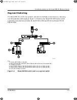
Page 17: ...connections Each switch can be used as a standalone device or can be used with 10 Mbps hubs or other interconnection devices in various configurations The configuration examples in this chapter illust...

Page 18: ...a file server Key 1 Server with 10 Mbps connection 2 Model SW108 Ethernet switch Normal Uplink push button set to Normal position 3 PCs with 10 Mbps connection Figure 3 1 Using the Model SW108 switch...

Page 19: ...del EN104 and Model EN108 Ethernet hubs Key 1 Server with 10 Mbps connection 2 Model SW108 Ethernet switch Normal Uplink push button set to Normal position 3 10 Mbps connection 4 Model EN104 Ethernet...

Page 20: ...SW108 BK Page 4 Friday June 27 1997 10 48 AM...

Page 21: ...in the following items Model SW108 Ethernet switch DC power adapter Warranty and Owner Registration Card This installation guide Call your reseller or customer support in your area if there are any wr...

Page 22: ...k push button The Normal Uplink push button eliminates the need to use a crossover twisted pair cable for daisy chaining or cascading Use the following guidelines to configure port 1 on the Model SW10...

Page 23: ...e rear panel of the switch and the other end of the power adapter cable to the wall outlet Verifying Installation When the installation is complete and power has been applied to the switch the followi...

Page 24: ...SW108 BK Page 4 Friday June 27 1997 10 48 AM...

Page 25: ...n two or more computers transmit data on the network simultaneously Computers that caused the collision retry transmission at different intervals until the transmission succeeds Excessive collisions c...

Page 26: ...cations as required by the 10BASE T standard Refer to Chapter C Cabling Guidelines for information on cable specifications Make sure the network adapter card installed in the PC is in working conditio...

Page 27: ...and Standard ISO IEC 802 3 ANSI IEEE 802 3i 10BASE T Ethernet Data Rate 10 Mbps Manchester encoded Interface RJ 45 connector for 10BASE T Ethernet interface Electrical Specifications Power Consumptio...

Page 28: ...ncondensing Operating altitude 10 000 ft 3 000 m maximum Storage altitude 10 000 ft 3 000 m maximum Electromagnetic Emissions Meets requirements of CE mark commercial FCC Part 15 Class A EN 55 022 CIS...

Page 29: ...T Mark Performance Specifications Frame filter rate 14 800 frames second maximum Frame forward rate 14 800 frames second maximum Network latency Less than 75 microseconds for 64 byte frames in store a...

Page 30: ...SW108 BK Page 4 Friday June 27 1997 10 48 AM...

Page 31: ...shielded twisted pair STP 100 cable and connects into the vista RJ 45 connector The vista RJ 45 connector also referred to as a 10 Mbps port is used to connect stations hubs and switches through UTP...

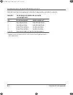
Page 32: ...ormal Uplink push button is in the Uplink position Table B 1 RJ 45 plug and vista RJ 45 connector pin assignments Pin Normal assignment Uplink assignment 1 Input Receive Data Output Transmit Data 2 In...

Page 33: ...ether because individual repeater port densities were often limited to 8 to 24 ports As structured wiring systems were implemented horizontal wiring from the wiring closet to the desktop was designed...

Page 34: ...tch ports are configured as media dependent interfaces with built in crossover ports called MDI X or normal ports Table C 1 Electrical requirements of Category 3 4 and 5 cables Specification Category...

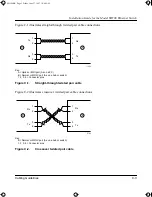
Page 35: ...DI X port As on a hub or switch 1 2 3 6 Connector pins Figure C 1 Straight through twisted pair cable Figure C 2 illustrates crossover twisted pair cable connections Key B Normal or MDI X port As on a...

Page 36: ...SW108 BK Page 4 Friday June 27 1997 10 48 AM...

Page 37: ...ices connecting to the switch 4 2 F FDX duplex toggle switches 2 4 4 3 5 1 FDX LED 2 3 5 1 features 1 3 front panel 2 1 full duplex mode 2 3 2 4 4 3 5 1 H half duplex mode 2 3 2 4 4 3 5 1 HDX duplex t...

Page 38: ...g 1 2 3 3 site preparation 4 1 straight through twisted pair cable 4 2 5 2 switches duplex toggle 2 4 4 3 switching technology 1 2 3 2 switching benefits of using 1 1 T technical specifications A 1 to...

Page 39: ...SW108 BK Page 3 Friday June 27 1997 10 48 AM...

Page 40: ...SW108 BK Page 4 Friday June 27 1997 10 48 AM...

Reviews: