background image

3G WiFi Router User Guide 

YML-O-3G19W

42 

www.netcomm.com.au

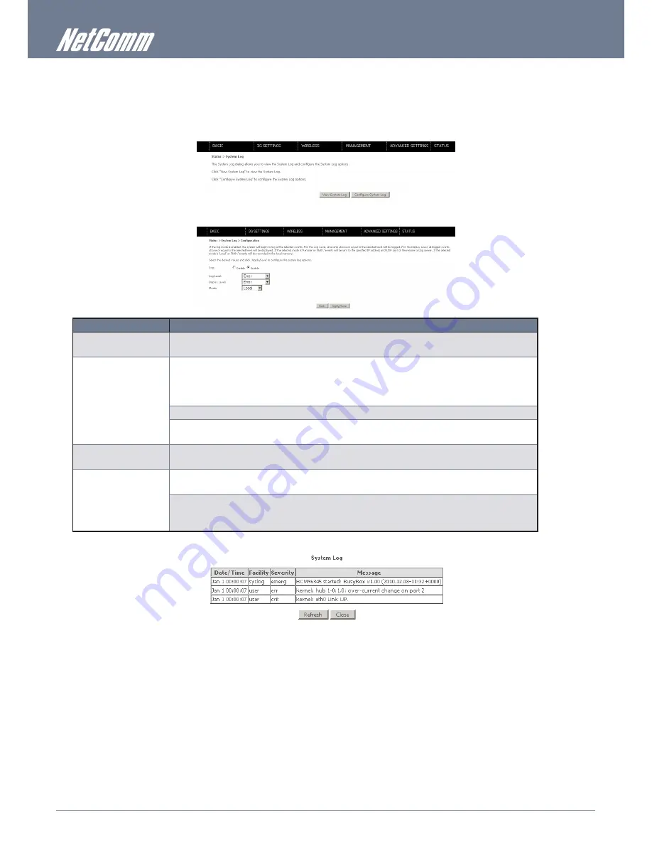
8.2 System Log

This function allows you to view system events and configure related options. Follow the steps below to enable and view the 


System Log.

1. 

Click Configure System Log to continue.

2. 

Select the system log options (see table below) and click Save/Apply.

OPTION

DESCRIPTION

Log

Indicates whether the system is currently recording events. You can enable or disable event logging. By default, it is 
disabled.

Log level

Allows you to configure the event level and filter out unwanted events below this level. The events ranging from the 
highest critical level “Emergency” down to this configured level  will be recorded to the log buffer on the Router’s 

SDRAM. When the log buffer is full, the newest event will wrap up to the top of the log buffer and overwrite the oldest 

event. By default, the log level is “Debugging”, which is the lowest critical level. The log levels are defined as follows:

Emergency is the most serious event level, whereas Debugging is the least important.

For instance, if the log level is set to Debugging, all the events from the lowest Debugging level to the most critical level 
Emergency level will be recorded. If the log level is set to Error, only Error and the level above will be logged.

Display Level

Allows you to select the logged events and displays on the View System Log window for events of this level and above 
to the highest Emergency level.

Mode

Allows you to specify whether events should be stored in the local memory, be sent to a remote syslog server, or to 
both simultaneously.

If remote mode is selected, the view systemlog will not be able to display events saved in the remote syslog server. 

When either Remote mode or Both mode is configured, the WEB UI will prompt you to enter the Server IP address and 

Server UDP port.

3. 

Click View System Log. The results are displayed as follows.

Summary of Contents for YML-O-3G19W

Page 1: ...YML O 3G19W 3G WiFi Router User Guide www netcomm com au 1 User Guide NETCOMM LIBERTY SERIES 3G WiFi Router ...

Page 2: ... the unit that offer exposure to air are not blocked Avoid using a telephone other than a cordless type during an electrical storm There may be a remote risk of electric shock from lightening Also do not use the telephone to report a gas leak in the vicinity of the leak Never install telephone wiring during stormy weather conditions Use an appropriate power supply preferably the supplied power ada...

Page 3: ...uration 17 5 Wireless 20 5 1 Setup 20 5 2 Security 21 5 3 Configuration 22 5 4 MAC Filter 23 5 5 Wireless Bridge 24 5 6 Station Info 24 6 Management 26 6 1 Device Settings 26 6 2 Configure SNMP agent 28 6 3 Simple Network Time Protocol SNTP 28 6 4 Access Control 29 6 5 Save and Reboot 30 7 Advanced Setup 32 7 1 Local Area Network LAN 32 7 2 Network Address Translation NAT 33 7 3 Security 35 7 4 Pa...

Page 4: ...Introduction ...

Page 5: ...de HSUPA HSDPA UMTS EDGE GPRS GSM module Four Ethernet LAN 10 100 Mbps connections Integrated Wireless IEEE 802 11g 54Mbps access point backward compatible with IEEE 802 11b WiFi Protected Access WPA WiFi Protected Access 2 WPA2 and 802 1x wireless encryption Static route Routing Information Protocol RIP RIP v2 routing functions Media Access Control MAC address and IP filtering Network Address Tra...

Page 6: ...sent traffic in either direction Internet Blue On Internet connection established Off No connection to the internet or router powered off Flashing Data being transmitted through the internet connection 3G Blue On Internet connection established Off No connection with UMTS cellular station no activity or router is powered off Flashing Connecting with UMTS 2G Blue On Internet connection established ...

Page 7: ...Quick Setup ...

Page 8: ...il you hear a click into the USIM slot at the back of the Router 4 Connect the yellow networking cable to one of the LAN ports found at the back of the Router 5 Connect the other end of the yellow networking cable to the port on your computer 6 Connect the power adapter to the Power socket on the back of the Router 7 Plug the power adapter into the wall socket and push the power button into the ON...

Page 9: ...Web User Interface ...

Page 10: ...ion profile in permanent storage can be created via the web user interface or telnet user interface or other management protocols The factory default configuration can be restored either by pushing the reset button for more than five seconds until the power indicates LED blinking or by clicking the Restore Default Configuration option in the Restore Default Settings screen 3 2 TCP IP Settings Your...

Page 11: ...Connection and select Properties 4 Left click on the Internet Protocol TCP IP item and then click Properties 5 Choose an IP address between 192 168 1 2 192 168 1 254 and enter this IP address into the IP Address field 6 Enter a Subnet mask of 255 255 255 0 and the IP address of the Router the default IP is 192 168 1 1 into the Default gateway fields 7 Enter the IP address of the Router the default...

Page 12: ...eft click on Manage Network Connections from the menu on the left hand side of the window For Windows 7 3 Left click on Change adapter settings from the menu on the left hand side of the window 4 Right click on the Local Area Connection item and left click on Properties 5 Left click on Internet Protocol Version 4 TCP IPv4 and click Properties 6 Choose an IP address between 192 168 1 2 192 168 1 25...

Page 13: ...f the router is 192 168 1 1 so the computer must be set with a different IP to the router In the case below the computer s IP address is set as 192 168 1 2 1 Click on the Apple menu and select System Preferences 2 In the System Preferences window click the Network icon and select the Ethernet connection For Windows Vista 3 From the Configure drop down list you can set your computer to Static IP mo...

Page 14: ...options available within the web user interface are based upon the device configuration and user privileges i e local or remote BASIC HOME The Basic Home screen is the WUI homepage and the first selection on the main menu It provides information regarding the firmware 3G and IP configuration of the device The following table provides further details FIELD DESCRIPTION Model Name The model name of t...

Page 15: ...3G Settings ...

Page 16: ...d should be provided by your Internet service provider or just leave it set to AUTO if not required If you have not received a username and password leave these fields empty Select IP compression and Data compression to be ON or OFF By default they are set to off 3 Click the Save button to save the new settings 4 Press the Connect button to reboot the router and to connect to Internet After reboot...

Page 17: ...ll your 3G service provider for assistance 4 3 1 PIN Code Protection PIN code protection prevents the use of a SIM card by unauthorized persons To use the 3G Mobile Broadband service with this router however the PIN code protection must be disabled If the SIM card inserted into the router is locked with a PIN code the web user interface will display the following screen after login PIN Lock Off If...

Page 18: ... you wish to change your PIN code for greater security enable the PIN Code protection Go to the previous section and follow the procedure listed under PIN Lock On After locking the SIM card select PIN Code Change and enter your Old and New PIN codes in the fields provided Keep in mind you only have 3 attempts before your SIM card is locked The remaining attempts number shows how many attempts are ...

Page 19: ...Wireless ...

Page 20: ... in Windows XP open Network Connections from the start Menu and select View Available Network Connections If the access point is hidden it will not be listed there To connect a client to a hidden access point the station must add the access point manually to its wireless configuration SSID 1 32 characters Sets the wireless network name SSID stands for Service Set Identifier All stations must be co...

Page 21: ... on your Wireless Security Card If the SSID does not match access is denied Network Authentication This option is used for authentication to the wireless network Each authentication type has its own settings For example selecting 802 1X authentication will reveal the RADIUS Server IP address Port and Key fields WEP Encryption will also be enabled WEP Encryption This option indicates whether data s...

Page 22: ...threshold which then triggers the RTS CTS mechanism Smaller packets are sent without using RTS CTS The default setting of 2347 maxlength will disable the RTS Threshold DTIM Interval Delivery Traffic Indication Message DTIM is also known as Beacon Rate The entry range is a value between 1 and 65535 A DTIM is a countdown variable that informs clients of the next window for listening to broadcast and...

Page 23: ...g Allow Permits access for the specified MAC addresses NOTE Add a wireless device s MAC address before clicking the Allow radio button or else you will need to connect to the Router s web user interface using the supplied yellow Ethernet cable and add the wireless device s MAC address Deny Rejects access for the specified MAC addresses MAC Address Lists the MAC addresses subject to the MAC Restric...

Page 24: ...ciate to the AP Bridge Restrict Selecting Enabled or Enabled Scan allows wireless bridge restriction Only those bridges selected in Remote Bridges will be granted access Enabled Scan scans the detected wireless networks and allows you to select one to connect to Click Refresh to update the station list when Enabled Scan is selected 5 6 Station Info The following screen appears when you select Stat...

Page 25: ...Management ...

Page 26: ...e the default settings of your Router It also provides a function for you to update your Routers firmware 6 1 1 Backup Settings The following screen appears when Backup is selected Click the Backup Settings button to save the current configuration settings You will be prompted to define the location of the backup file to save to your PC 6 1 2 Update Settings The following screen appears when selec...

Page 27: ...the reset button The device board hardware and the boot loader support the reset to default button If the reset button is continuously pushed for more than 5 seconds and not more than 12 seconds the boot loader will erase the configuration settings saved on flash memory 6 1 4 Update Firmware The following screen appears when selecting Update Firmware By following the steps on the page you can upda...

Page 28: ...P agent 1 Open a web browser IE Firefox Safari type in LAN address of the router http 192 168 1 1 by default to log into the web interface 2 The login username and password by default is admin admin 3 Go to Management SNMP 4 Enable SNMP agent and set up all options according to your requirements 5 Press Save Apply to activate the settings 6 3 Simple Network Time Protocol SNTP This screen allows yo...

Page 29: ...lustrated below The following access services are available FTP HTTP ICMP SNMP TELNET and TFTP Enable or disable these options are per your requirements Click Save Apply to continue 6 4 2 Passwords The Passwords option configures your account access password for your Router Access to the device is limited to the following three user accounts admin is to be used for local unrestricted access contro...

Page 30: ...cessary to reconfigure your TCP IP settings to adjust for the new configuration For example if you disable the Dynamic Host Configuration Protocol DHCP server you will need to apply Static IP settings on your connected devices NOTE 2 If you lose all access to your web user interface simply press the reset button on the rear panel for 5 7 seconds to restore the default settings ...

Page 31: ...Advanced Setup ...

Page 32: ... DHCP Server Select Enable DHCP server and enter your starting and ending IP addresses and the lease time This setting configures the router to automatically assign the IP address default gateway and DNS server addresses to every DHCP client on your LAN Option 42 66 150 160 These options are used for special DHCP setup Static IP Lease List To specify the IP address assigned through DHCP according ...

Page 33: ...ined service is selected the port ranges are automatically configured External Port End Enter the ending external port number when you select Custom Server When a predefined service is selected the port ranges are automatically configured Protocol User can select from TCP TCP UDP or UDP Internal Port Start Enter the internal port starting number when you select Custom Server When a predefined serv...

Page 34: ...the port ranges are automatically configured Trigger Protocol TCP TCP UDP or UDP Open Port Start Enter the starting open port number when you select custom application When an application is selected the port ranges are automatically configured Open Port End Enter the ending open port number when you select custom application When an application is selected the port ranges are automatically config...

Page 35: ... IP Filter The default setting for Outgoing traffic is ACCEPTED Under this condition all outgoing IP packets that match the filter rules will be BLOCKED To add a filtering rule click the Add button The following screen will display OPTION DESCRIPTION Filter Name The Filter rule label Protocol TCP TCP UDP UDP or ICMP traffic Source IP address Enter source IP address Source Subnet Mask Enter source ...

Page 36: ... traffic is BLOCKED Under this condition only those incoming IP packets that match the filter rules will be ACCEPTED To add a filtering rule click the Add button The following screen will display NOTE Please refer to the Outgoing IP Filter table for field descriptions Click Save Apply to save and activate the filter ...

Page 37: ...your local time 7 4 1 Time of Day Restrictions This enables you to select a time of the day to impose or relax any network restrictions you have in place Click Add to display the following screen OPTION DESCRIPTION User Name A user defined label for this restriction Browser s MAC Address MAC address of the PC running the browser Other MAC Address MAC address of another LAN device Days of the Week ...

Page 38: ...add a new URL filter You can then enter the URL and the port number as prompted on the page to enter a new URL filter and click Save Apply 7 5 Routing Static Route settings can be found in the Routing link as illustrated below 7 5 1 Static Route The Static Route screen displays the configured static routes Click the Add or Remove buttons to change settings Click Add to display the following screen...

Page 39: ...ur Router 7 6 1 Dynamic DNS The Dynamic DNS service allows a dynamic IP address to be aliased to a static hostname in any of a selection of domains allowing the router to be more easily accessed from various locations on the internet NOTE The Add Remove buttons will be displayed only if the router has been assigned an IP address from the remote server To add a dynamic DNS service click the Add but...

Page 40: ...Status ...

Page 41: ...s on the Help screen OPTION DESCRIPTION Test your ENET 1 4 Connection Pass Indicates that the Ethernet interface from your computer is connected to the LAN port of this Router Fail Indicates that the Router does not detect the Ethernet interface on your computer Test your Wireless connection Pass Indicates that the wireless card is ON Down Indicates that the wireless card is OFF Ping Primary Domai...

Page 42: ...y default the log level is Debugging which is the lowest critical level The log levels are defined as follows Emergency is the most serious event level whereas Debugging is the least important For instance if the log level is set to Debugging all the events from the lowest Debugging level to the most critical level Emergency level will be recorded If the log level is set to Error only Error and th...

Page 43: ...MM band The 2G radio frequency band which supports Quad band GSM GRPS frequencies including GSM850 GSM900 DCS1800 PCS1900 with each number representing the respective frequency in MHz GMM PS state Packet Switching state MM CS state Circuit Switching state Signal Strength The 3G 2G service signal strength in dBm Signal Level RSSI 3G Radio Signal Strength Index Quality Ec Io The total energy per chi...

Page 44: ...ckets in bytes Pkts Rx TX receive transmit packets Errs Rx TX receive transmit packets with errors Drops Rx TX receive transmit packets dropped 8 4 2 3G Statistics Click 3G network in the Statistics submenu to display the screen below Inbound Octets Number of received octets over the interface Packets Number of received packets over the interface Drops Received packets which are dropped Error Rece...

Page 45: ...st R reinstate route ford ynamic routing D dynamically installed by daemon or redirect M modified from routing daemon or redirect Metric The distance to the target usually counted in hops It is not Used by recent kernels but may be needed by routing daemons Service Shows the name for the WAN connection Interface Shows connection interfaces 8 6 ARP Click ARP to display the ARP information FIELD DES...

Page 46: ...PC network name MAC Address Shows the Ethernet MAC address of the device host PC IP address Shows IP address of device host PC Expires In Shows how much time is left for each DHCP Lease 8 8 PING The PING menu provides feedback of connection test to an IP address or a host name Input an IP address or a host name e g www google com and press Submit The connection test result will be shown as below ...

Page 47: ...Appendix ...

Page 48: ...relocate the receiving antenna Increase the separation between this equipment and the receiver Connect the equipment to an alternate power outlet on a different power circuit from that to which the receiver TV is connected Consult an experienced radio TV technician for help 3 The power supply that is provided with this unit is only intended for use with this product Do not use this power supply wi...

Page 49: ...County Code Selection feature is disabled for products marketed in the US Canada Operation is subject to the following two conditions 1 this device may not cause interference and 2 this device must accept any interference including interference that may cause undesired operation of the device This Class B digital apparatus complies with Canadian ICES 003 Cet appareil numérique de la classe B est c...

Page 50: ...e detailed terms of this license The following parts of this product are subject to the GNU GPL and those software packages are copyright by their respective authors Linux 2 6 21 system kernel busybox_1_00_rc2 bridge utils 0 9 5 dhcpcd 1 3 ISC DHCP V2 P5 syslogd spread from busybox wireless tools ntpclient of NTP client implementation GNU Wget Availability of source code Please visit our web site ...

Page 51: ...anger that redistributors of a free program will individually obtain patent licenses in effect making the program proprietary To prevent this we have made it clear that any patent must be licensed for everyone s free use or not licensed at all The precise terms and conditions for copying distribution and modification follow GNU GENERAL PUBLIC LICENSE TERMS AND CONDITIONS FOR COPYING DISTRIBUTION A...

Page 52: ...xception the source code distributed need not include anything that is normally distributed in either source or binary form with the major components compiler kernel and so on of the operating system on which the executable runs unless that component itself accompanies the executable If distribution of executable or object code is made by offering access to copy from a designated place then offeri...

Page 53: ...umber of this License you may choose any version ever published by the Free Software Foundation 10 If you wish to incorporate parts of the Program into other free programs whose distribution conditions are different write to the author to ask for permission For software which is copyrighted by the Free Software Foundation write to the Free Software Foundation we sometimes make exceptions for this ...

Page 54: ...duct either by the way of power supply or communication line whether caused by thunderstorm activity or any other cause s 3 The fault is the result of accidental damage or damage in transit including but not limited to liquid spillage 4 Your product has been used for any purposes other than that for which it is sold or in any way other than in strict accordance with the user manual supplied 5 Your...

Page 55: ...only covers the basic installation and features outlined in the Quick Start Guide For further information regarding the advanced features of this product please refer to the configuring sections in the User Guide or contact a Network Specialist DYNALINK NZ 12c Tea Kea Place Albany Auckland New Zealand P 09 448 5548 F 09 448 5549 E sales dynalink co nz W www dynalink co nz Trademarks and registered...

Reviews: