background image

SB72 User's Manual,  350030-006 


Page 14


Testing with a Telnet Connection 

 
One way to quickly test the functionality of your serial-to-Ethernet connection is with the Telnet program 
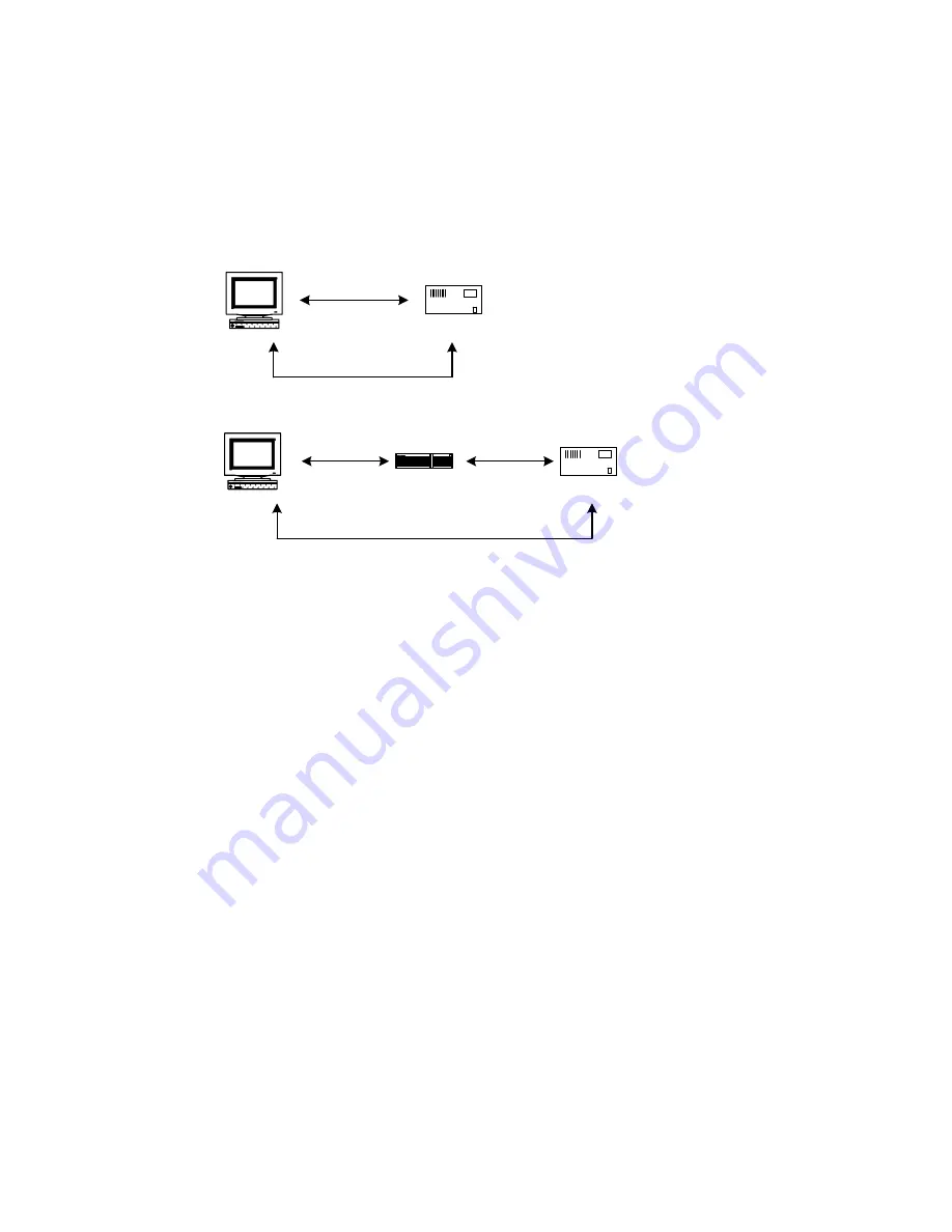
and an RS-232 serial terminal program. To run the test, configure your system as one of the two examples 
shown below: 


The objective of this example is to use a single host computer running telnet and a serial terminal program 
to send data in either direction. If you type text in the telnet window, it should appear in the serial terminal 
window. For a serial terminal you can use Hyper Terminal, or download MTTTY from the NetBurner web 
site. 
 
In the following examples an IP Address of 10.1.1.2 will be used for the SB72. Replace this number with 
your specific IP Address you assigned during configuration. 
 
1.


Connect the hardware in one of the above configurations 

2.


Open a command prompt window on the Host Computer.  

3.


Verify everything is connected correctly by executing "ping 10.1.1.2". You should see a valid ping 
response. 

4.


Run Telnet by typing: "telnet 10.1.1.2 9221". This assumes a default port number of 9221. You can 
replace this default port number with the port number you assigned during configuration. 

5.


Run Hyper Terminal or MTTTY. Set the baud rate to the value you assigned the SB72 during 
configuration. The default is 115,200. 

6.


At this point anything you type in Telnet should appear in the serial terminal window and vice versa. 


Host Computer

SB72

Hub

Host Computer

Cross-wired

Ethernet Cable

Ethernet Cable

Ethernet Cable

SB72

RS-232 Cable, Null-

Modem Configuration

RS-232 Cable, Null-

Modem Configuration

Summary of Contents for SB72

Page 1: ...SB72 User s Manual 350030 006 e t B u r n e r SB72 User s Manual Revision 1 6 November 13 2007...

Page 2: ...ion Examples 5 RS 232 5 RS 485 5 Network Configuration 6 Operational Configuration 7 Device Network Settings 7 Device Connection Settings 8 Serial Data Port Settings 9 Connector Descriptions 10 Specif...

Page 3: ...configuration will depend on whether you want to use RS 232 TTL or RS 485 There are 2 serial ports Ports that can be configured by jumpers on the board and through the web interface This manual will r...

Page 4: ...OPEN X JP5 OPEN OPEN or 2 3 CTS 2 3 CLOSE 1 2 OPEN X Key X don t care Open No connection Closed Jumper pins Note for RS 232 Operation The SB72 can run 2 channels without hardware handshaking If RTS an...

Page 5: ...onfiguration Examples RS 232 Remove all jumpers Install Jumper JP3 Optional Install Jumpers JP4 and JP5 on pins 2 3 for RTS CTS handshaking RS 485 Remove all jumpers Install Jumper JP2 Install Jumper...

Page 6: ...illuminated if not correct any cabling errors Note that IPSetup uses a UDP broadcast protocol similar to BOOTP and will not operate through a router 4 If your network supports DHCP The assigned IP ad...

Page 7: ...s of the SB72 device If DHCP is selected the SB72 will obtain IP address information automatically including the net mask gateway and DNS server If Static is selected you need to supply the static IP...

Page 8: ...er will disconnect the current TCP IP connection and allow the new incoming connection request to connect Outgoing Connections If this option is enabled the SB72 will initiate a connection to an outsi...

Page 9: ...0 RS 232 or TTL Port 1 RS 232 or TTL Port 0 RS 485 Half Duplex Port 0 RS 485 Full Duplex Data Baud Rate Selects the baud rate of the serial data channel Data Bits Select number of data bits Data Parit...

Page 10: ...GND 3 FD RX 4 GND 5 VCC 5V 6 GND 7 FD TX HD 8 GND 9 FD TX HD 10 GND J3 Factory Test Connector Dual Row 16 Pin Header For factory use only J4 SPI Interface Connector Single row straight header Pin Sig...

Page 11: ...adapter wiring information is provided in the RS 232 NULL Modem Wiring section of this manual Pin Signal Pin Signal 1 NC 2 Short to 7 3 RX1 4 RTS1 or TX0 5 TX1 6 CTS1 or RX0 7 Short to 2 8 NC 9 GND 10...

Page 12: ...echanical PCB Dimensions 3 25 x 2 4 Mounting holes RS 232 NULL Modem Wiring The following table and diagram show how to create a null modem cable adapter for RS 232 connections A null modem cable will...

Page 13: ...31 255 255 Class B 192 168 0 0 to 192 168 255 255 Class C If you are doing development on an isolated network you can use the following addresses Set Your PC s Network Adapter Card IP Address to 10 1...

Page 14: ...2 Replace this number with your specific IP Address you assigned during configuration 1 Connect the hardware in one of the above configurations 2 Open a command prompt window on the Host Computer 3 Ve...

Page 15: ...Mouser Electronics Authorized Distributor Click to View Pricing Inventory Delivery Lifecycle Information NetBurner SB72 301CR...

Reviews: