background image

2.2   Clock Source 

Clock source refers to the timing origination for E1 transmission links. 


2.2.1   Local (default-provider mode)


Timing is derived from an oscillator on board the EIM2000. 
 

2.2.2   Loop (default-subscriber mode)


Timing is derives from an intermediate device on the E1 line. 


2.3   Frame Type 

Frame type is the E1 data encapsulation method. A frame consists of 248 bits (8-bit samples of 

each of the 31 E1 data channels plus a synchronization bit) transmitted at a rate of 8,000 frames 
per second (1,984 kbps) across the E1 line. EIM2000 frame type configuration options are Cyclic 
Redundancy Check or No Cyclic Redundancy Check. 


2.3.1   Cyclic Redundancy Check (default)


Cyclic Redundancy Check (CRC) detects line errors and scrutinizes data integrity across the E1 

line by appending a CRC character to the end of each data block. The character is a 
hexadecimal value calculated from the contents of the data block; if a different value is 
calculated at the receiving end than was appended at the originatation point, retransmission is 
requested. 


2.4   Line Code 

Line code is the E1 mode of transmission. The two line code options for the EIM2000 both fall within 
the International Telecommunication Union - Telecommunication Standardization Sector (ITU-T) 
G.703 Standards for Transmission Facilities. 


2.4.1   High Density Binary 3 (default)


High Density Binary 3 (HDB3) line encoding uses bipolar violations to guarantee the presence 
of pulses in the E1 line thereby helping to prevent loss of synchronization between the 
EIM2000 and remote E1 equipment. HDB3 accommodates the minimum ones density 
requirement in the European public network. 


2.4.2   Alternate Mark Inversion


Alternate Mark Inversion (AMI) alternates positive and negative pulses across the E1 line. 

Although AMI links typically encounter long strings of zeros which can potentially cause loss of 
synchronization between E1 units, Net to Net Technologies' E1 products meet the European 
minimum ones density requirement internally such that, even with AMI, loss of synchronization 
is prevented between the EIM2000 and remote E1 equipment, just as it is with HDB3. 


N

OTE

Local timing is the default for an EIM2000 in E1 provider mode. Default for an EIM2000 in subscriber mode is 
Loop and cannot be modified. 

210-0000054 rev0

2

 EIM2000 User Guide Page 18 of 20

Summary of Contents for EIM2000

Page 1: ...003 Net to Net Technologies Inc The Net to Net Logo is a trademark of Net to Net Technologies Inc Worldwide Headquarters Net to Net Technologies 112 Corporate Drive Portsmouth NH 03801 USA 1 877 638 2...

Page 2: ...ch the Velcro Strap and Position the E1 Cable RJ21 Connector s 1 4 1 3 Secure the Connector s 1 4 1 4 RJ21 Port Pinouts 1 4 2 Remote Connection 1 4 2 1 Loop Bonded Connection 1 4 2 2 Single Line E1 Co...

Page 3: ...dling this equipment The EIM2000 houses a bank of eight 8 switches at the rear of the module opposite the faceplate Switches are numbered from left to right 1 8 Switches 1 and 4 8 are not used NOTE EI...

Page 4: ...such as the EIM2000 and slots 13 14 are reserved for MUMs Interface modules may be placed in any order in slots 1 12 The IPD4000 and IPD4000E are five slot chassis slots 1 4 are reserved for interfac...

Page 5: ...1 3 2 Slide the EIM2000 Firmly into the Chassis DO NOT USE EXCESS FORCE 210 0000054 rev02 EIM2000 User Guide Page 5 of 20...

Page 6: ...ure the EIM2000 in the IP DSLAM Chassis Tighten the fastening screws on the module faceplate with a Philips or Flathead screwdriver If your IP DSLAM is not yet powered up refer to the IP DSLAM Install...

Page 7: ...000E has two 2 corresponding RJ21 connectors located on the back of the chassis The bottom row of RJ21 connectors A on the IPD12000E provides the E1 connection for EIM2000 ports 1 12 and the top row o...

Page 8: ...nd B Connectors in order to utilize all 24 E1 ports EIM2000 12 For the EIM2000 12 connect an E1 cable to the A Connector only the B Connector has no function for the EIM2000 12 IPD12000E IPD12000E NOT...

Page 9: ...ot to which an E1 connection can be made This connection will support E1 ports 1 12 on both the EIM2000 12 and the EIM2000 24 you will not be able to utilize ports 13 24 on an EIM2000 24 installed in...

Page 10: ...ward leaving it looped under the bottom edge of the connector frame Slide the RJ21 connector of your E1 cable underneath the Velcro from the left and press it firmly into the RJ21 connector on the cha...

Page 11: ...are using a 120 or 180 cable both the right and left sides of the cable connector should be secured to the RJ21 connector frame on the chassis Pull the Velcro strap downward making sure that it is sn...

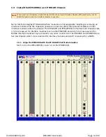
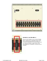
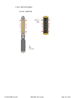
Page 12: ...1 4 1 4 RJ21 Port Pinouts 1 4 1 4 1 RJ21 Pins E1 RJ21 Connector EIM2000 RJ21 Port 210 0000054 rev02 EIM2000 User Guide Page 12 of 20...

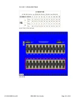
Page 13: ...PD4000E left side IPD12000 and IPD4000 EIM2000 E1 PORTS 1 2 3 4 5 6 7 8 9 10 11 12 RJ21 PINS TX Ring 14 15 16 17 18 19 20 21 22 23 24 25 Tip 39 40 41 42 43 44 45 46 47 48 49 50 RX Ring 1 2 3 4 5 6 7 8...

Page 14: ...e s between the EIM2000 and any of the remote E1 equipment is greater than 6 000 feet the line s may require an E1 repeater B CONNECTORS IPD12000E top row and IPD4000E right side EIM2000 E1 PORTS 13 1...

Page 15: ...t http www nettonet com support docs 230 0000035 1 4 2 2 Single Line E1 Connection A single line connection can be established between the EIM2000 and any of Net to Net s E1 modems 1 4 3 Verify the Co...

Page 16: ...the outgoing connection from the E1 port has also been lost then the remote E1 modem will have LOS as well RX Reception flashing amber E1 activity The port is receiving data from the remote E1 modem s...

Page 17: ...onal UNLESS the LK LED remains unlit as well in which case the E1 port has LOS solid amber Remote Alarm Indication RAI An outgoing connection has been lost the remote E1 modem is not receiving any dat...

Page 18: ...Code Line code is the E1 mode of transmission The two line code options for the EIM2000 both fall within the International Telecommunication Union Telecommunication Standardization Sector ITU T G 703...

Page 19: ...le parameter configuration 3 2 Data Storage Upon initial power up of the IP DSLAM default parameters of the EIM2000 will remain in place unless changed via NMS CLI or SNMP Once changed new configurati...

Page 20: ...ldwide Headquarters Net to Net Technologies 112 Corporate Drive Portsmouth NH 03801 USA 1 877 638 2638 http www NetToNet com Contact NetToNet com EMEA Headquarters Net to Net Technologies Victoria Hou...

Reviews: