background image

DVR User’s Manual


16 

3.2.1  

User Management 

The DVR provides the option to create up to seven sets of usernames and 
passwords with customized authority, excluding the preset “admin” account. 
From the Main Menu, select <System Setup> 

Æ

 <User Management> and 

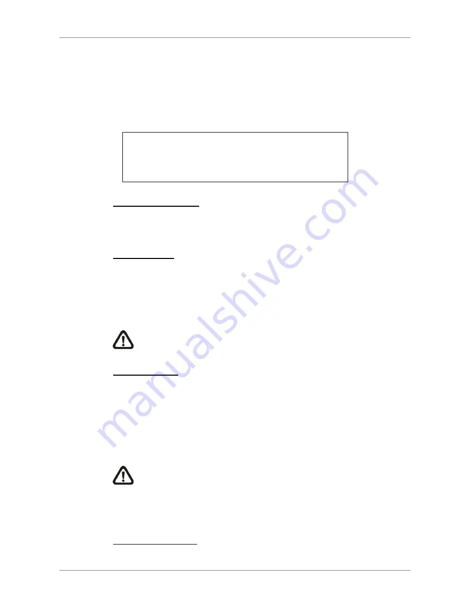
the menu is as the following: 
 

User Management 

1. Password Protection 
2. Account Setup 
3. Authority Setup 
4. Load Default Setting 

ON 


No  


Password Protection 

Select <ON> to request for username and password for accessing functions 
listed in Authority Setup menu, or select <OFF> to allow free access.   
 

Account Setup


Setup customized username, password, and authority level in this menu. The 
username is case sensitive. The authority level rank from level 1~8, and level 
8 has highest authority. Alternatively, select <Disable> to stop using the 
account. 
 

NOTE:

 The username and authority level of the preset “admin” 

account cannot be changed. 

 
Authority Setup


Setup the allowed authority level for accessing the functions listed in this 
menu. The functions include: Playback/Search, Dome Control, Call Control, 
Export Data, Menu Access, System Setup, Monitor Setup, Camera Setup, 
Record Setup, Sequence Setup, Event Setup, Database Setup, Configuration, 
Text Setup, and Shutdown. The authority level rank from level 1~8, and level 
8 has highest authority. Alternatively, select <Disable> to allow free access. 
 

NOTE:

 The “Menu Access” cannot be set to <Disable>. 


When the account does not have authority to access certain functions, an 
error message will be displayed on the screen. 
 

Load Default Setting


Select <Yes> to load the default setting. 

Summary of Contents for Ultimate Premium H.264

Page 1: ...Ness Ultimate Premium H 264 DVR User s Manual REV1 2 Sep11 ...

Page 2: ...ectric shock When cleaning is necessary shut down the system and unplug the unit from the outlet before uncovering the top cover Do not use liquid cleaners or aerosol cleaners Use only a damp cloth for cleaning Always shut down the system prior connecting or disconnecting accessories with the exception of USB devices This symbol intends to alert the user to the presence of important operating and ...

Page 3: ...our dealer for assistance Rack Mounting Consult with the supplier or manufacturer of your equipment rack for the proper hardware and procedure of mounting this product in a safe fashion Avoid uneven loading or mechanical instability when rack mounting units Make sure that units are installed to get enough airflow for safe operation The maximum temperature for rack mounted units is 40 C Check produ...

Page 4: ... 3 Power On Shutdown the Unit 17 3 4 System Date Time Setting 18 3 4 1 Set Date Time 18 3 4 2 Daylight Saving Time 19 3 4 3 Network Time Protocol Setup 20 3 6 Record Schedule Quality Setting 24 3 6 1 Schedule Setup 24 3 6 2 Preset Record Configuration 25 3 6 3 Per Camera Configuration 25 3 6 4 Record Event Video Only 26 3 6 5 ezRecord Setup 26 3 6 6 Data Lifetime 27 3 6 7 Pre Alarm Recording 27 3 ...

Page 5: ...elect the External Device 40 4 4 1 2 Select Video for Exporting 41 4 4 1 3 Digital Signature 42 4 4 1 4 Erase Disc 42 4 4 2 Quick Video Export through Front Panel 42 4 4 2 1 ezBurn Introduction 42 4 4 2 2 Export Normal Video 43 4 4 2 3 Export Event Video 44 4 5 Dome Control 44 4 5 1 Dome Connection 44 4 5 2 Dome Protocol Setup 45 4 5 3 RS485 Setup 45 4 5 4 Dome Controlling Key 46 4 5 5 Set Preset ...

Page 6: ...58 5 3 2 2 Playback Instant Recorded Video 58 5 3 3 Playback Video 59 5 3 3 1 Playback Remote Video 59 5 3 3 2 Playback Local drv Files 60 5 3 3 3 Playback Controls 60 5 3 4 Verify Digital Signature 61 5 3 5 Search from Event List 61 5 3 6 Take a Snapshot 61 5 3 7 Remote Monitoring Software Trouble Shooting Guide 62 Appendix A Recommended HDDs 63 Appendix B Remote Controller 64 Appendix C USB Mous...

Page 7: ...et on PCs or mobile devices and backup the configuration and video data MEANWHILE recording simultaneously The Premium H 264 DVR is pre installed with remote viewing and configuration software which is a Web browser plug in allowing users to view live or recorded video images and enables remote configuration The remote software is stored in the Premium H 264 DVR and deployed over a LAN WAN or Inte...

Page 8: ...m overheating The maximum allowable temperature of operating environment is 40 C The unit utilizes heat conducting techniques to transfer internal heat to the case especially to the bottom side of the unit NOTE Be sure the rubber feet are not removed and always leave a space for air ventilation on the unit s bottom side 2 2 Select Video Format The DVR is designed to operate under either NTSC or PA...

Page 9: ...ll monitor is used to display full screen video of all installed cameras in sequence The BNC call monitor connector allows user to connect the DVR with a call monitor VGA Output VGA output connectors are offered for connecting to VGA main monitors Some models provide one while other models provide two VGA connectors Digital Output Dual VGA VGA Digital Output A digital output connector is provided ...

Page 10: ...al USB devices to the unit such as ThumbDrive DVD RW or a USB mouse Audio Out Optional The DVR provides two types of connectors for connection to audio output devices such as amplified speakers One is a RCA connector to output audio associated with the main monitor The other is an optional terminal block providing connections with all channels for the purpose of two way audio talk function Refer t...

Page 11: ...ing Call mode Dome Control mode Playback mode Freeze mode and Sequence mode will be displayed on the bottom left corner of the screen The date time information will be display on the bottom right corner of the screen Ch4 1 2008 11 09 PM04 31 22 3 1 Front Panel Introduction The front panel controls enable users to control the unit and preset the programmable functions 3 1 1 LED Definition The LEDs ...

Page 12: ...orresponds to the number of cameras supported by the unit In Dome Control mode the key 1 is used to access the Set Go preset menu the key 2 is used to hide or display the dome camera setting parameters COPY In Playback mode press COPY to select the start and end time of the export video Refer to section Video Export for detailed information CALL In Live mode press this key once to control the call...

Page 13: ... recording of video Press FREEZE again to return to live mode Press FREEZE while playing the recorded video the playback video will be paused Press LEFT RIGHT to move the recorded video reverse forward by single step Press FREEZE again to continue playing video SEQ Sequence Press to start automatic sequence display of video from all installed cameras MENU Press this key to enter the OSD setup menu...

Page 14: ...p the function of certain keys including PLAY MENU SEARCH and DOME Once users lock up the function of these keys correct password must be entered before accessing the functions of these keys NOTE Please go to the Password menu to enable or disable the password protection JOG SHUTTLE for specified models The jog shuttle knob shown as the figure on the right is a combination of a shuttle ring with a...

Page 15: ...ncel OK The next step is to enter a corresponding password The preset password for admin is 1234 Password Verification _______ Press Channel Keys To Enter Password 4 8 Digits Press Key To Delete NOTE It is strongly suggested to change the preset password to prevent unauthorized access to the unit An icon displayed at the center bottom of the screen will show the authority level of the account Unde...

Page 16: ...evel rank from level 1 8 and level 8 has highest authority Alternatively select Disable to stop using the account NOTE The username and authority level of the preset admin account cannot be changed Authority Setup Setup the allowed authority level for accessing the functions listed in this menu The functions include Playback Search Dome Control Call Control Export Data Menu Access System Setup Mon...

Page 17: ...nitor and then disappear when the unit has been completely powered up To Restart Shutdown the Unit Press MENU and input the username and password that has sufficient authority to access the OSD setup menu Select Shutdown in Main Menu and press ENTER to enter the Shutdown menu which displays as follows Shutdown 1 Power Off 2 Reboot Execute Execute Power Off Select this item to shut down the unit Do...

Page 18: ...work Time Protocol Setup 2008 02 21 PM10 39 26 OFF 1 Row Y M D 24 HR Date First 3 4 1 Set Date Time Set Date Time Select Date or Time and press ENTER for adjusting the settings LEFT RIGHT keys are used to move the cursor to previous or next field ENTER is for selecting and UP DOWN are used to change the value in the selected field NOTE The new date time setting applies to record new video The date...

Page 19: ...me The item is for people who live in certain regions to observe Daylight Saving Time Select ON to enable or OFF to disable the function If the function is disabled the DST Start End time and DST Bias will be grayed out and cannot be accessed NOTE If this function is enabled the date time information will be shown on the screen with a DST icon when playing back recorded video or searching video in...

Page 20: ...appear Select the Network Time Protocol Setup to set the time server The default time server is time nist gov but the user can change it to other time servers when desired A list of IP addresses of the time servers is listed below 129 6 15 28 129 6 15 29 132 163 4 101 132 163 4 102 132 163 4 103 128 138 140 44 192 43 244 18 131 107 1 10 69 25 96 13 206 246 118 250 208 184 49 9 64 125 78 85 207 200...

Page 21: ...DVR User s Manual 21 This page is intentionally blank ...

Page 22: ...DVR User s Manual 22 This page is intentionally blank ...

Page 23: ...DVR User s Manual 23 This page is intentionally blank ...

Page 24: ...uality 0 Days 15 Sec ON ON 3 6 1 Schedule Setup The Schedule Setup is used to set the day and night time or weekend recording schedule Select Schedule Setup from the Record Setup menu and press ENTER the following menu is displayed Schedule Setup 1 Day Time Start 2 Day Time End 3 Night Time Start 4 Night Time End 5 Weekend Schedule 6 Weekend Start 7 Weekend End AM06 00 PM06 00 PM18 00 AM06 00 ON F...

Page 25: ...cessing these schedules The menu is displayed as below Record Mode 720 240 120PPS in NTSC 720 288 100PPS in PAL Per Camera Config Cameral Select Normal PPS Normal Qlty Event Max PPS Event Qlty Event Act Day 7 5 Mid 30 Best Both Night 7 5 Mid 30 Best Both CH1 Weekend 7 5 Mid 30 Best Both First select a Camera for setting its record configuration The image and recording settings from the selected ca...

Page 26: ...low figure ezRecord Setup How Many Days To Record Daytime Record Night Record Weekend Record Average Normal PPS Average Normal Quality 2 Days Yes Yes Yes 15 Best Follow these steps to Setup ezRecord Select How Many Days To Record and press ENTER then press UP DOWN to choose an option The average normal PPS Quality will be adjusted automatically The maximum of days depends of the size of the instal...

Page 27: ...to select this item in Record Setup menu and then use UP DOWN keys to set the data lifetime The value ranges from 1 to 365 days or select 0 to disable the function NOTE To play back a video exceeding the data lifetime please extend the duration until the recording data time of the video is included 3 6 7 Pre Alarm Recording This item is used to set the recording duration of pre alarm video The pre...

Page 28: ...m allows user to enable disable Audio recording function of the unit When it s set to ON audio input is recorded and saved with the video When it s set to OFF audio is ignored 3 6 10 Purge Data This item is used to delete the Normal or Event recording video In Record Setup menu move the cursor to Purge Data and press ENTER the Purge Data menu is displayed Purge Data 1 Purge All Data 2 Purge All Ev...

Page 29: ...c camera images and recorded to the DVR To enable this function enter OSD Setup menu with proper account and select Text Setup Press Enter and the following OSD setup menu will show up Text Setup 1 Text Function 2 Text Overlay 3 Exception Text Setup 4 Input Setup ON Live PB 3 7 1 Text Function This item is used to enable disable this function Select ON the text database will be created on the hard...

Page 30: ...as exceptions By Numerals Exception String must be defined before By Numerals takes effect If By Numerals is enabled only transactions which meet both Exception String and By Numerals creteria will be marked as exceptions The selections are as the following OFF The function is disabled Specific When the value of a transaction meets a specific value it will be marked as an exception That specific v...

Page 31: ...set and 2 Trigger is ON The data stored before hand will not be marked as exceptions 3 7 4 Input Setup This item is used to configure the connection settings of the POS device Input Setup 1 Port Selection 2 Input Source 3 Camera Selection 4 Text Filter 5 Manual Filter Setup 6 Input Process 7 Text Baud Rate 8 Text Bits 9 Text Stop 10 Text Parity Serial Port Direct Connected 1 ASCII Canonical 9600 8...

Page 32: ... Posiflex ICD 2002 POS X Xr500 Posiflex PD 302 Samsung SRP350 Posiflex PD 303 Sensor TP 288 Posiflex PD 2100 Star TSP100 futurePRNT Posiflex PD 2200 Star TSP600 POS X Xp8000 Star TSP700 Scales Star TSP800 Sibnet TPG Axiohm A794 STAR SCD400 PD WP 520 ESC POS Soteke VFD2025 Soteke VFD2029 TEC Toledo 8217 TYSSO VFD Series Ultimate Technology PD1100XL Wedderburn DS 770 Manual Filter Setup Once enter t...

Page 33: ...versatile ways of viewing both live and recorded video Following presents these view formats Viewing in Full Screen Press any CHANNEL key directly to view the corresponding camera image in full screen format Viewing in Multi window Various multi window view formats are offered for selection To switch between available viewing formats press MODE repeatedly The available view formats are illustrated...

Page 34: ...while viewing live image the image pauses but the date time information does not and the system clock continues running Press FREEZE to pause the live image press FREEZE again to resume the live camera view 4 1 4 View Recorded Video To view recorded video user can press PLAY key directly After pressing the PLAY key the unit starts to continue playing back the recorded video from the suspended poin...

Page 35: ...o pause the playback video When the recorded video is paused press LEFT RIGHT to resume playback video single step reverse forward respectively Press FREEZE again to continue playing video z PLAY Press it to start playing back video exit current mode or stop playing back video and return to live mode Pause Playback and Single Step Forward To pause and resume recorded video follow these steps Press...

Page 36: ...Users are allowed to use the front panel of the DVR to control a call monitor display without having to access the Main menu Two viewing modes can be displayed on call monitor Sequence display and Single camera display To program the call monitor sequence see OSD Setup Manual Section Sequence Setup Follow the steps to control the call monitor Press the CALL key on the front panel to enter call mon...

Page 37: ...ve the cursor to From Time and press ENTER will start playing recorded video from the specified From Time Move the cursor to End Time and press ENTER will start playing recorded video from the specified End Time Use Direction keys to move the cursor for setting the start time Adjust the date and time values by UP DOWN keys Press ENTER to confirm the settings or ESC to abort Move the cursor to Begi...

Page 38: ... triggered camera and alarm type As some events are deleted others are displayed The latest recorded event video will be listed on the top Follow these steps to search event video through Event List Press SEARCH to enter the Search menu To search event video that has been recorded on a specific camera use LEFT RIGHT to move the cursor and press ENTER to select or de select a channel Move the curso...

Page 39: ...o sets of word strings Search for videos with data containing EITHER ONE of the word strings AND Enter two sets of word strings Search for videos with data containing BOTH of the word strings Specific Specify one set of word string Search for videos with data containing the specific word string By Numerals Outside The Range Enter two numbers to specify a range Search for videos with data containin...

Page 40: ...nd readme txt Make sure an external storage device is available and connected to the appropriate port for video export From the Main menu select Video Export and press ENTER The menu is displayed as below Video Export 1 Select Device 2 Select Ch 3 From 4 To 5 Select Events 6 Data Type 7 Export Format 8 Digital Signature 9 Erase Disc 10 Begin Export CH1 CH2 CH3 CH4 2008 03 19 AM07 50 05 2008 03 28 ...

Page 41: ...egins and ends Move the cursor using LEFT RIGHT keys and press ENTER to select the date time items adjust the selected date and time value by UP DOWN keys Select Events Select this item to display the event list Move the cursor to scroll through the event list and press ENTER to select event s to be exported Data Type The item is used to select exporting video type The options are Normal export no...

Page 42: ...R to start deleting data 4 4 2 Quick Video Export through Front Panel Through front panel control the DVR allows users to easily export wanted video as drv file with the built in DVD RW or to an external device such as a USB ThumbDrive To export video to an external device make sure the device is connected to the DVR NOTE Once an external device has been connected to the DVR the device has priorit...

Page 43: ...fter entering playback mode play the video and press COPY once to mark the starting point of the export video The playback continues Press COPY again to mark the ending point of the export video Then the ezBurn window will display as below figure The information shown on the window is read only ezBurn confirmation Selected Device Built in DVD RW All data on the disc will be erased Exported Require...

Page 44: ...arning message will be shown on the screen 4 5 Dome Control The DVR allows user to control a dome camera by the front panel In Live mode user can press CHANNEL key to display the desired dome camera in full screen To enter dome control mode press the DOME key and press channel key 2 to display the hint screen To exit the dome control mode and return to live mode press ESC or DOME In dome control m...

Page 45: ...ocol associated with dome camera using the Direction keys and ENTER The available protocol includes DSCP AD422 Pelco D Pelco P Fastrax 2 JVC Panasonic_C Panasonic_N and None NOTE The settings become effective after saving the changes and exiting from the menu 4 5 3 RS485 Setup The DVR controls the dome cameras via RS 485 communication protocol The RS 485 parameters of the DVR must be set to the sa...

Page 46: ...sed to enter the Dome Preset menu to set up certain position as a preset and go to the predetermined preset positions for viewing Toggle Hint Screen This function is used to avoid viewing the dome parameter information while controlling dome camera Press this key to hide the screen Press it again to redisplay the screen Iris Open Use to open the Iris on the dome camera Focus Near Use to focus the ...

Page 47: ...epends on the dome manufacturer Follow the steps to set preset points Press a Channel key to view the corresponding camera in full screen Then press DOME to enter dome control mode Then a Hint Screen shown as below figure will display on the screen Press 2 to hide the dome control Hint Screen press 2 again to toggle the Hint Screen Use Direction keys to position the dome camera to desired position...

Page 48: ...reset points Press a Channel key to view the corresponding camera in full screen Then press DOME to enter dome control mode Then a Hint Screen shown as blow figure will display on the screen Press 2 to hide the dome control Hint Screen press 2 again to toggle the Hint Screen Press 1 to access the Set Go Preset function Dome Preset First Page Index 1 2 3 4 5 6 7 Set Preset No No No No No No No Go P...

Page 49: ...art speaking to the camera site press and hold the DOME key Once the DOME key is released the audio from the camera site will be heard again To terminate intercom press the same channel key or press ESC NOTE Intercom function is not available for channel 1 4 7 UPnP Function UPnP is the abbreviation for Universal Plug and Play which is a relatively new technology that integrates a universal protoco...

Page 50: ...n internet browser that connects to the DVR via the remote control software 4 7 2 UPnP NAT Traversal Function The UPnP NAT traversal function will help to automatically setup a router if the DVR connects to the internet via a router When a PC connects to a DVR not in the same local area network a real IP address and corresponding port number is required However if the DVR is behind a router the co...

Page 51: ...the remote monitoring software The tasks can be performed with the remote monitoring software are listed below Remote viewing of live recorded video Remote setup of the DVR Remote control of dome cameras Alarm notification from the DVR Up to five connections to one DVR using the remote monitoring software including the preset admin and four other accounts 5 1 Remote Monitoring System Requirements ...

Page 52: ...k the IP address of the DVR To check the IP address press MENU key on the unit and enter username and password to access OSD setup menu Select System Setup Network Setup then LAN Setup to check the IP Start the IE it can be started either by clicking on the desktop icon or by using the Start menu to access it NOTE Windows IE provides the ActiveX component that is required when using the remote mon...

Page 53: ...lick OK to confirm the setting and close Trusted sites dialog In the Security Level area click Custom Level The Security Settings screen is displayed Under ActiveX controls and plug ins set all items to Enable or Prompt Click OK to apply the setting and close the Security Settings screen Click OK to close Internet Options dialog Now the installation can continue to the next step ...

Page 54: ...lick Yes to accept ActiveX plug ins The remote monitoring software plug ins will be downloaded and installed on the PC automatically when the connection is successfully made NOTE Do not enter any leading 0 characters in the address for example 192 068 080 006 should be entered as 192 68 80 6 If the default trigger port 80 is changed into another one take port 81 for example the IP address should b...

Page 55: ...lowing steps demonstrate procedures to view video from remote unit Start the remote monitoring software by entering the IP Address of the DVR in the Address bar of the browser Alternatively click on the Favorite entry for the unit if the IP address of the unit has been set Enter the Username and password The login username and password can be saved to ease future login The default username and pas...

Page 56: ...nitoring Remotely When a DVR is successfully connected the main window of the remote monitoring software will be displayed Please refer to the Setup Guide for the graphical illustration of functional items The functions on the remote monitoring software will be described in the following sections 5 3 1 View Live Video View live video from the cameras attached to the DVR by clicking Live button on ...

Page 57: ...Panel are described as follows Set Preset Set Preset is used to set up preset positions The remote monitoring software allows its user to set up to 255 preset positions with DSCP American Dynamics Fastrax JVC Panasonic C N and Pelco Pelco P Pelco D dome cameras Use Direction buttons to move dome camera to an appropriate position and then click the button and choose wanted number from the pull down...

Page 58: ...s in the directions to be viewed 5 3 2 Instant Recording The Instant Recording function allows users to record video quickly to the PC NOTE The Audio function is set to OFF as the default setting 5 3 2 1 Record Video Instantly Follow the steps to start recording instantly Click on the Instant Recording button Select the destination folder to save the video Click on the button again to stop recordi...

Page 59: ...emote Playback tab The Remote Playback screen will be displayed The From and To in the Available Record Video display the date and time from which recorded video is available for playback To playback remote video segments follow these steps Choose Playback in Select field for playback recorded video In Start field users can change the date and time either by typing desired numbers directly or by u...

Page 60: ...ack controls To end the playback click Live to return to live video 5 3 3 3 Playback Controls When the local or remote video is being played the remote monitoring software is in Playback Mode The playback controls toolbar will emerge on the main window toolbar The Playback controls and indicators are described as below Icon Name Description Fast Backawad Step Backward 1 Click to play the recorded ...

Page 61: ...rmation about the alarm events that the unit recorded and saved Up to 1024 events can be listed in the Event List The Event List displays each event by its number the date and time of the event the type of the event including Alarm In Motion Detection Video Loss and Over Speed and the camera channel where the event occurred To view an event video follow these steps Click SEARCH button positioned i...

Page 62: ...epeatedly please follow the steps to delete the temporary internet files Select Tools from the main menu of the web browser then Internet Options and then click the General tab Click the Delete Files button in the Temporary Internet Files field the Delete Files screen displays as below Check the Delete all offline content box and click OK Now enter the IP address of the DVR to make the connection ...

Page 63: ...50G Barracuda 7200 10 ST3500630AS 500G Barracuda 7200 10 ST3750640AS 750G Barracuda 7200 11 ST3500320AS 500G Barracuda 7200 11 ST31000340AS 1000G Barracuda ES 2 ST3500320NS 500G Seagate Barracuda ES 2 ST31000340NS 1000G Hitachi DeskStar HDP725032GLA360 320G Maxtor DiamondMax 22 STM3500320AS 500G WD AV WD1600AVJS 160G WD AV WD2500AVJS 250G WD AV WD3200AVJS 320G WD AV WD5000AVJS 500G WD AV WD7500AVV...

Page 64: ...DVR User s Manual 64 Appendix B Remote Controller A remote control is provided for the DVR The function keys on the remote control are listed as below figure DVR Control mode Dome Camera Control mode ...

Page 65: ...hange the DVR Unit ID to any number between 224 and 239 and exit the menu The ID Table is listed below for reference DVR Unit ID 224 225 226 227 228 229 230 231 Remote Control 1 2 3 4 5 6 7 8 DVR Unit ID 232 233 234 235 236 237 238 239 Remote Control 9 10 11 12 13 14 15 16 After the DVR Unit ID is changed setup the DVR SEL of the remote control Press DVR SEL and then press the Remote Control immed...

Page 66: ... to display viewing modes 2x2 3x3 and 4x4 Click on P to display the previous viewing mode Click on S to switch monitor control to the second main VGA monitor Clicking the left button of the USB mouse functions the same as pressing the ENTER key on the front panel of the DVR Clicking the right button of the USB mouse functions the same as pressing the ESC key on the front panel of the DVR The scrol...

Page 67: ...DVR User s Manual 67 Appendix D Keyboard Access Sketch The following sketch shows the keys used to access and control the connected DVR ...

Page 68: ...tput models VGA Digital Output Simultaneous Output Resolution Digital Output VGA BNC Main BNC Call S Video Hybrid Display on VGA Playback On VGA Dual Main Enabled 800 X 600 O O O O O O O Enabled 1024 X 768 O O O O O Enabled 1280 X 1024 O O O O O Disabled 800 X 600 O O O O O O For dual VGA models Dual VGA Simultaneous Output Resolution VGA 1 VGA 2 BNC Main BNC Call S Video Hybrid Display on VGA 2 P...

Page 69: ...tle ring clockwise counterclockwise causes the unit to playback faster forward backward According to the rotating angle the shuttle ring users can choose the playing speed from 1 2 4 8 16 and 32 in both forward and reverse directions shown as below figure Inside the shuttle ring is the jog disk shown as below figure It can turn in either direction Once the video is paused users can use the jog dis...

Page 70: ...ification in the interest of ongoing product development and improvement 2011 Ness Corporation Pty Ltd ABN 28 069 984 372 Head Office Ness Security Products Pty Ltd ABN 28 069 984 372 Ph 61 2 8825 9222 Fax 61 2 9674 2520 ness ness com au Sydney Ph 02 8825 9222 Fax 02 9674 2520 sales ness com au Melbourne Ph 03 9875 6400 Fax 03 9875 6422 nessmelb ness com au Brisbane Ph 07 3399 4910 Fax 07 3217 971...

Reviews: