background image


User Manual 

Ness IQ-MDVR-4 – Mobile Black Box Recorder. 


11

User default password is 22222222, and Admin password is 88888888. 

When the OPERATOR PASSWORD IS CORRECTLY entered permissions are limited to video,   

    sensor menu. 

When the ADMIN PASSWORD IS CORRECTLY entered permissions are full access to MDVR.   

When  the  SUPER  PASSWORD  IS  CORRECTLY  entered  full  access  to  MDVR  under  the 

circumstance of losing the password and modifies the MAC address. 


When Password is set to ‘disable’, press the SETUP key on the handheld controller to access the setup 

menu directly; 


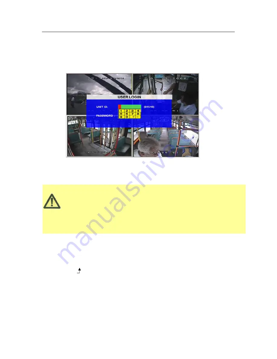
When Password is set to ‘enable’, press LOGIN/LOCK OR ENTER key on the handheld controller for the 

setup menu to appear: 


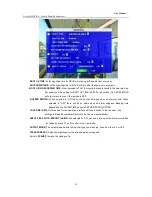
UNIT ID: The unit ID of MDVR. You enter the ID setting in the GUI and then the numbers will display on screen 

automatically.   

PASSWORD: Enter the admin password or user password. 


Keyboard: Press 

Enter

to use keyboard to type device ID and password. 

1

0~9, number key, press

Enter

to select the number. 

2

123: Input type shift key. (Number, capital, small letter) 

3

delete, 


Exit.   


Summary of Contents for IQ-MDVR-4

Page 1: ...User Manual Ness IQ MDVR 4 GUI Mobile Digital Video Recorder ...

Page 2: ...ght to revise and improve its products All specifications are therefore subject to change without any notice The purpose of this manual is to aid the user for the operation for our IQ MDVR especially for GUI setting The user should have a basic understanding of computer operation and basic knowledge of how to connect peripherals and make some settings ...

Page 3: ...P 10 5 SEARCH and PLAYBACK VIDEO FILE 12 5 1 ALL FILES 12 5 2 EVENT FILES 15 6 SETUP 17 6 1 SYSTEM 17 6 1 1 DATA TIME 18 6 1 2 GENERAL 19 6 1 3 REGISTER INFO 21 6 1 4 FORMAT 22 6 1 5 UPGRADE 22 6 1 6 USER SECURITY 24 6 1 7 CONFIG 26 6 1 8 SYSTEM LOG 26 6 1 9 GEO FENCING 27 6 2 RECORD 27 6 2 1 OPTIONS 28 6 2 2 OSD OVERLAY 30 6 2 3 CAMERA SETTING 32 6 2 4 RECORD SETTINGS 32 6 2 5 SUB STREAMING 33 6 ...

Page 4: ...4 Mobile Black Box Recorder 4 6 4 4 ACCELERATION 45 6 4 5 TEMPERATURE 46 6 4 6 CAMERA 46 6 4 7 VOLTAGE 47 6 5 PERIPHERAL 48 6 5 1 PTZ 48 6 5 2 EXT COM SETUP 49 7 INFORMATION 50 7 1 1 SYSTEM 50 7 1 2 HISTORY 51 7 1 3 MODULES 52 ...

Page 5: ...e in most efficiency way 4 channels for high fidelity digitally recorded synchronized audio matched to 4 video channels User friendly criteria to playback the events associated video only Dual Stream for wireless transmission depends on wide or narrow bandwidth User selectable settings for quality and audio record enable disable for each video channel 12v power supply for multiple devices such as ...

Page 6: ...ding module and display on screen control menu Numeric Input Keys Use the numbers to input Values in the system setup Screen or switch through the channels in live view Navigation Arrows Use the ARROW keys to move between selections input fields and icons Press ENTER to select And EXIT to return Next and previous is also used to increase or decrease volume when at live or search screens ...

Page 7: ...n password 88888888 POWER To reset the MDVR in to sleep mode You can press power button again to let MDVR start up when it in sleep mode Switch full screen of one channel to quad view Brightness contrast color adjustment for per channel Use button to change the values You have to adjust the values for each channel individually SETUP Login GUI to setup the parameters EXIT Return to the previous men...

Page 8: ...modes available FWD Fast forward the video while playback X2 and X4 modes available CF No use at present F1 Export all the event record files of the day to USB by press F1 key F2 F3 F4 Reserved for future use 2 4 PTZ FUNCTION KEYS While connect with PTZ camera and using the RS485 in DB26 following commands can control with PTZ camera with following function ZOOM IN ZOOM OUT ZOOM IN OUT IRIS IRIS B...

Page 9: ...User Manual Ness IQ MDVR 4 Mobile Black Box Recorder 9 3 MENU TREE Menu structure tree ...

Page 10: ...DD SD card first and then lock it in front panel Refer to HDD Installation Instructions of how to install the HDD into the HDD Caddy For testing just connect the red wire and yellow wires together to Power 8 36V DC and connect the black wire to GND However when installed in a vehicle please connect red wire to power yellow wire to Ignition black GND wire to power SYSTEM LOGIN FOR SETUP ...

Page 11: ...odifies the MAC address When Password is set to disable press the SETUP key on the handheld controller to access the setup menu directly When Password is set to enable press LOGIN LOCK OR ENTER key on the handheld controller for the setup menu to appear UNIT ID The unit ID of MDVR You enter the ID setting in the GUI and then the numbers will display on screen automatically PASSWORD Enter the admin...

Page 12: ...ord time and file type Highlight the option ALL FILES which will display the following screen FILE SOURCE User can choose to playback from the HDD or from the SD for mirror recording FILE TYPE The type of the file including all files alarm file and normal file CHANNEL Select the channel you want to search DATE MDVR system will display the current day automatically The days with recorded files will...

Page 13: ...or listing out all the certain video files depends on the setting for the file type date and time SEL For selecting the files for backup Please press arrow key on remote control to select the file that need to back up and then will display REV Press for selecting all the other files For example if you do not select any file for backup then press REV which will then select all files If you select o...

Page 14: ...creen will pop up If the MDVR current video type is different to the setting that the MDVR recorded previously then the video file cannot playback For example if the video type of recorded files is NSTC and now the setting of video type is PAL then you won t be able to playback the video file until you change the video type to NSTC Another example if you change the video type to NTSC then after th...

Page 15: ...it allows you to search for all the event file LOG and not the video file FILE TYPE The type of the alarm file includes I O ACCELERATION SPEED TEMP VL ALARM MOTION DETECTION BLIND and so on DATE MDVR system will display the current date automatically The date with alarm record files will be indicated in yellow Press SEARCH to enter into the next menu to list all the video files based on the File s...

Page 16: ... EVENT NAME The name of the alarm such as video loss alarm over speed alarm low speed high temperature alarms etc DATE Displays the date when the alarm occurred TIME The start time when the alarm occurred REV Press REV to select For example if you do not select any files to be backed up then press REV all the files will be selected EX LOG Export the selected LOG to the external USB device from the...

Page 17: ...ress ENTER The screen will show the menu as shown below Once a setting is made press SAVE to make all the setting valid Once saved you will be provided with confirmation the setting has been applied If a Network setting change is made once you exit to live view the MDVR will automatically reboot to allow the settings to take affect The MDVR will stop recording when it is placed into the MDVR confi...

Page 18: ...me Protocol the device must have network access connection and assign the NTP IP location This process runs at 6 30am local time while the system has network connection TIME ZONE Please choose the correct time zone where vehicle is SYNC TIME This is the time when the unit will sync the system time every day The method depends on the setting on the TIME SYNC SOURCE option NTP SERVER IP Input the IP...

Page 19: ...et to Ignition you can also program a shut down delay function For example If you setup the SHUT DOWN DELAY as 5 min then MDVR will shut down after 5 min after the ignition is turned off B TIMER If set to timer the MDVR will automatically turn on and off at the time you specify If you select TIMER then the following screen will be shown C IGNITION OR TIMER means both conditions can apply ...

Page 20: ...ilt in buzzer will beep when an alarm occurs When selected to OFF there will be no audio when an alarm happens Beeping time depends on the ALARM TIME as set in SETUP RECORD OPTION IDLE TIME SEC Sets the time for the operation interface will take to switch to the live view If no settings is made the system will switch to the live view automatically EVENT FILES AUTO EXPORT USB When selected to ON yo...

Page 21: ...key on the remote control to highlight this Option and then input the name of the company VEHICLE NO The number of the vehicle DRIVER ROUTE NAME The driver s name and the route name DEVICE ID This ID should be unique and it is very important for the message server of CMS WCMS and ADS Only this number can be recognized by message server NOTE When you connect MDVR to PC software make sure vehicle NO...

Page 22: ...ge SD USB Then choose format method there are three methods optional FAST FORMAT MDVR would clear all the video data directly SLOW FORMAT MDVR will scan and detect the device before formatting If there are bad blocks it will tag them and bypass them when recording Detect Video Storage MDVR just detect the media for recorded video storage media and no format will occur After format is successful th...

Page 23: ...is completely successful HOW TO UPGRADE THE FIRMWARE 1 Create a folder named dvrupgrade in thumb USB drive then copy the firmware upgrade file into this folder 2 Insert the thumb drive into the USB port in the front panel of MDVR 3 Select this firmware update option by pressing UPGRADE The IQ MDVR will begin the upgrade 4 During the firmware upgrade then following screen will pop up 5 After the up...

Page 24: ...owing MCU UPGRADE Upgrading the MCU is the same as upgrading the firmware 6 1 6 USER SECURITY Sets up the password for user and admin PASSWORD ENABLE When selected to ON a password will be required to access setup menu When selected to OFF no password is required to access the setup menu USER PASSWORD User can only search but can t modify any parameters ADMIN PASSWORD An Administrator User Level h...

Page 25: ...ss IQ MDVR 4 Mobile Black Box Recorder 25 The password must be entered twice to confirm before it can be set If the password does not match a password error will be displayed Scroll to SAVE to make the setting valid ...

Page 26: ...ackup to the external device IMPORT Imports the MDVR configuration file to the current device Insert the external storage device to the USB port Must have configuration file in the storage device and then press IMPORT The configuration will be imported to this MDVR automatically NOTE All data is imported except the MAC address LOCAL IP WIFI IP and register information RESTORE Restore default setti...

Page 27: ... device to the USB port and then press EXPORT then the configuration file will backup to the external device IMPORT THE GEO FENCING CONFIG FILE Import the MDVR GEO Fencing configuration file to the current device Please insert the external storage device to the USB port Must have configuration file in the storage device and then press IMPORT The configuration will be imported to this MDVR automati...

Page 28: ...RE REC TIME 1 60 MIN Pre record time setting is from 1 to 60 minutes For example If the setting for pre record is 30min when an alarm trigger at 10 30 then the record file start from 10 00 to 10 30 will pack as alarm record Make sure the Pre recording switch is ON as set in next page when you want to use this function ALARM DURATION 3 30 SEC Sets the alarm duration time Any alarm of the same type ...

Page 29: ...ile save time 7 10 15 20 30 45 days option where during the save time the locked recording file won t be deleted Once the lock time is passed the recording file LOCK identifier will be from L to U which will then allow it to be deleted PRE RECORDING SWITCH Only when this is sent as ON will the pre recording time be valid SD CARD TYPE Internal means the SD card is inserted in the slot below the HDD...

Page 30: ... TIME Display date and time on OSD ALARM Display Alarm information on OSD FIXED means show the alarm information all the time on image ACCEL DATA Display the information for inertial sensor TEMPERATURE Display the temperature on OSD FIRMWARE VER Display the current firmware version GPS INFO Display the GPS working status TRIGGER means only when GPS is available it will be shown CHANNEL NAME Displa...

Page 31: ...User Manual Ness IQ MDVR 4 Mobile Black Box Recorder 31 SPEED Display vehicle speed info If all the options are ON Then the following screen will pop up after you press Enter during live view ...

Page 32: ...d the live view ROUND Means channel loop function Sequential switching mode If you set the round time as 5 seconds the channel will display in full screen mode for this time VOICE INTERCOM it s a switch for talk function It can only be initiated from the server side e g via CMS NOTE The audio of 4 th channel is used for this function So when using the voice intercom then audio on camera 4 cannot b...

Page 33: ...his is used for video transmission to WCMS software which won t affect the recording on MDVR There are two modes SUB STREAM mode 1 is for broad bandwidth such as connect in LAN or WIFI mode 2 is for wireless transmission like GPRS or 3G When you selected MODE1 and then press SURE you will enter into the interface as follow EN Enable this channel or not If it is OFF then you can t get video from th...

Page 34: ...means it will adjust the bit rate and frame according to the bandwidth of network fix means it will transmit as the bit you setup when the bandwidth is not enough the video may not smoothly 6 2 6 SCHEDULE Date Press ENTER to change the period of time to control the recording schedule Single Day Choose the name of a day to create a recording schedule Every Day Choose Every to apply a schedule to ev...

Page 35: ... day in the period There is no need to overlap times of Schedule 1 and Schedule 2 Ending at 23 59 of one day and beginning with 00 00 of the next day will provide continuous recording without interruption factory default setting 6 2 7 OTHER SETTING A INITIALIZE INTERFACE LIVING will set for live view image on an LCD monitor CP3 MENU is to show the CPS setting menu when using a CP3 monitor B WATERM...

Page 36: ...AYER Press ENTER to enable the exporting of the MINIPLAYER to the USB thumb drive This allows video to be played back using this mini player when played on other PC s 6 3 NETWORK 6 3 1 SERVER The sever IP and port setting is used with CMS Center Management System software ...

Page 37: ...C running the CMS software The MDVR communicates to CMS via LAN or WIFI on a local network or via 3G wireless module PORT please use the default port 5556 MEDIA SERVER IP AND PORT This is for future use 6 3 2 LOCAL NETWORK The Local IP is the IP setting for the IQ MDVR The IP address must be a fixed address to use the Network capabilities Use NUMERIC keypad to enter the TCP IP address information ...

Page 38: ...ique and cannot be changed 6 3 3 WIFI SETUP When turned on the following screen will be displayed GET IP TYPE There are two options STATIC IP means you will need to manually program a static IP for the MDVR to connect to your WIFI server or AUTO IP means it will get a dynamic IP DHCP IP Enter the static IP address of built in WIFI SUB Enter the subnet mask GATE Enter the gateway that the MDVR will...

Page 39: ... module type here GPRS CDMA EVDO WCDMA EDGE TD WCDMA NONE Note This must be the same settings as your 3G module 2 ACTIVE MODE You may choose the active mode to trigger 3G live view transmission Always 3G transmission will keep connected once the MDVR is power up Call SMS 3G transmission will be triggered when anyone of the 3 preset mobile phones calls or sends message to the SIM card number in MDV...

Page 40: ...AL PARAMETER Check the setup as per the following form but the parameters should be different in different countries so please check with your network carrier for the 4 parameters 4 INTERCOM FUNCTION This setting enables and disables the intercom function in CP3 ...

Page 41: ...ual Ness IQ MDVR 4 Mobile Black Box Recorder 41 5 FTP SETTING The MDVR can work as a FTP server so user can type the MDVR s IP address in IE address bar to login the MDVR and copy the video files out 6 4 EVENT ...

Page 42: ...ter into the soft keyboard The label also identifies the type of event when doing a quick search using EVENT SEARCH option SET LOW normal close means low voltage will trigger the alarm HIGH normal open means a higher voltage will trigger the alarm ALARM Press ENTER to select between OFF or ON ON means when the sensor is triggered the alarm LED will flashing until re logging in with a system with a...

Page 43: ... SENSOR OUTPUT Our MDVR support 2 sensor outputs two sensor outputs are on the I O HUB All the alarm inputs can trigger the three sensor output such as sensor1 8 over speed temperature video loss and so on please enter into GUI SETUP EVENT SENSOR OUTPUT as follow ...

Page 44: ... be connected to MDVR to receive satellite signals for speed For more information on capturing speed from speedometer please contact local distributor for more technical support CALIBRATE Speed check is used to calibrate the offset speed when connected to the speedometer That s to say the check only available when speed source is vehicle Input the first area with the vehicle speed for example at 8...

Page 45: ...alarm OSD To name the event for example you can name the over speed event as SPDH and low speed as SPDL Whenever the event triggers SPDH or SPDL will show in OSD EN To enable the alarm when this kind of event triggers Threshold The threshold defined the speed For example if we define 80KPH as high speed once the speed equals or is higher than this amount it would be activate it as an alarm file AL...

Page 46: ... normally under the temperature below 0 Deg C 6 4 6 CAMERA Display the alarm information from camera MOTION DETECTION SETTING This is to set the Channel which will be used for motion detection and the channel for blind detection sensitivity and sensitive area OSD This to provide the name the alarms caused by different kinds of camera triggers For example MD for motion detection BD for blind detect...

Page 47: ...function LOW VOLTAGE setup the low Voltage limit value for MDVR to shut down VOLTAGE OF START setup the voltage parameter for MDVR to reboot TIME FOR SHUTDOWN means when MDVR voltage is low for this period the device will shutdown automatically INTERVAL TIME FOR CMS means when MDVR voltage is low for this period the device will disconnect to CMS server ALARM FOR PANIC BUTTON This is to set the pan...

Page 48: ... BAUD RATE select the different baud rate for your PTZ there are 1200 2400 4800 and 9600 DATA BIT select how many data bits the system will use There are 5 6 7 8 options to select default setting is 8 STOP BIT select how many stop bits the system will use There are 1and 2 to select the default setting is 1 VERIFY there are None Odd Even Mark Space to select the default setting is none ADDRESS Fill...

Page 49: ... external accessory connection used for connecting PTZ Inertia sensor LED screen station announcement and so on MODE There are two options being STANDARD and BUS MODE When select as standard mode you can select each external port for each COM when select Bus mode COM1 is station announcement COM2 is amplifier board COM3 and COM4 is changeable ...

Page 50: ...1 1 SYSTEM Displays the MCU version firmware version hard disk information 1 NONE HDD means No HDD is installed or the HDD is defective and isn t working 2 NO FORMAT means HDD installed but not formatted 3 Showing the detailed information for HDD means HDD is working fine ...

Page 51: ...User Manual Ness IQ MDVR 4 Mobile Black Box Recorder 51 7 1 2 HISTORY The data for history information Press CLEAR to delete all the current data ...

Page 52: ...User Manual Ness IQ MDVR 4 Mobile Black Box Recorder 52 7 1 3 MODULES Display the module information GPS and WIFI Ness Corporation www nesscorporation com ...

Reviews: