background image

1.3.3 

User's liability

To guarantee optimum operation of the system, you 

must abide by the following instructions:

Read and follow the instructions given in the manuals 

provided with the appliance.

Call on a qualified professional to carry out installation 

and initial commissioning.

Get your installer to explain your installation to you.

Have the required inspections and maintenance car­

ried out by a qualified installer.

Keep the instruction manuals in good condition close 

to the appliance.

1  Safety

7641178 - v03 - 25072017

EFU FF

9

Summary of Contents for EcoNox EFU 22 FF

Page 1: ...EASYLIFE SUSTAINABLE COMFORT Neovo MW 8000040 3 en User Guide Oil fired boiler NeOvo EcoNox EFU 22 FF EFU 29 FF ...

Page 2: ...using the product and keep it in a safe place for later reference In order to ensure continued safe and efficient operation we recommend that the product is serviced regularly Our service and customer service organisation can assist with this We hope you enjoy years of problem free operation with the product ...

Page 3: ...Control 17 5 1 Browsing in the menus 17 5 2 Start up 17 5 3 Shutdown 17 5 3 1 Switching off the heating 17 5 3 2 Stopping domestic hot water production 18 5 3 3 Shutting down the installation 18 5 4 Frost Protection 18 6 Utilisation with the control panel IniControl 2 19 6 1 Browsing in the menus 19 6 2 Start up 19 6 2 1 Description of the PCBs 20 6 2 2 Selecting a PCB 20 6 3 Shutdown 21 6 3 1 Swi...

Page 4: ...3 Venting the installation 36 10 Troubleshooting 37 10 1 Error messages B Control 37 10 1 1 Error code display 37 10 1 2 Fault code display 37 10 2 Error messages IniControl 2 37 10 2 1 Error messages 37 10 2 2 Accessing the error log 37 11 Environmental 39 11 1 Disposal and Recycling 39 11 2 Energy savings 39 12 Warranty 40 12 1 General 40 12 2 Terms of warranty 40 13 Appendix 41 13 1 Product fic...

Page 5: ...ermitted to in stall the boiler in accordance with prevailing local and national regulations Important Allow the space required to correctly install the boiler Refer to the Overall space needed for the boiler section in the installation and service man ual Warning Do not touch the flue gas pipes Depending on the boiler settings the temperature of the flue gas pipes may exceed 60 C Warning Do not t...

Page 6: ...rer its after sales service or per sons with similar qualifications in order to obviate any danger Important The installation must comply on all points with prevailing regulations and directives which gov ern work and interventions in individual homes blocks of flats and other buildings Caution The boiler must always be connected to the pro tective earthing Earthing must comply with the prevailing...

Page 7: ... etc that govern works and interventions in individual homes blocks of flats or other buildings Note Keep the boiler accessible at all times Caution Install the boiler in a frost free environment Note Regularly check the presence of water and pres sure in the heating installation Important Never remove or cover labels and data plates af fixed to the appliances Labels and data plates must be legibl...

Page 8: ...ay not be invoked in the following cases Failure to abide by the instructions on installing the appliance Failure to abide by the instructions on using the appli ance Faulty or insufficient maintenance of the appliance 1 3 2 Installer s liability The installer is responsible for the installation and initial commissioning of the appliance The installer must ob serve the following instructions Read ...

Page 9: ...als provided with the appliance Call on a qualified professional to carry out installation and initial commissioning Get your installer to explain your installation to you Have the required inspections and maintenance car ried out by a qualified installer Keep the instruction manuals in good condition close to the appliance 1 Safety 7641178 v03 25072017 EFU FF 9 ...
Page 10: ...rsonal in jury Caution Risk of material damage Important Please note important information See Reference to other manuals or pages in this manual 2 1 2 Symbols used on the appliance 1 Alternating current 2 Protective earthing 3 Before installing and commissioning the appliance carefully read the instruction manuals provided 4 Dispose of used products through an appropriate recovery and re cycling ...

Page 11: ...etroleum products Fatty Acid Methyl Esters used as heating fuel 3 2 Technical data Tab 2 Technical parameters for boiler space heaters Product name EFU 22 FF EFU 29 FF Condensing boiler No No Low temperature boiler 1 Yes Yes B1 boiler No No Cogeneration space heater No No Combination heater No No Rated heat output Prated kW 22 30 Useful heat output at rated heat output and high tem perature regime...

Page 12: ... power level indoors LWA dB 52 53 Emissions of nitrogen oxides NOX mg kWh 118 118 1 Low temperature means for condensing boilers 30 C for low temperature boilers 37 C and for other heaters 50 C return temperature at heater inlet 2 High temperature regime means 60 C return temperature at heater inlet and 80 C feed temperature at heater outlet See The back cover for contact details 3 Technical speci...

Page 13: ...t oil burner Electronic control panel Flue gas discharge via a forced flue type connection 4 2 Main components 4 2 1 Boiler 1 Control panel 2 On Off switch 3 Access to the burner manual reset button 4 Data plate 4 3 Description of the control panel B Control 4 3 1 Description of the keys Heating temperature setting button Level access key Information Installer or Chimney Sweep Manual reset key Dom...

Page 14: ...e domestic hot water parameters raising the value 4 MODE display accessing the menu selected or confirming the value modifi cation 4 4 2 Description of the display Burner Operation Burner ON Operating modes Steady symbol heating function enabled Flashing symbol heating production running Steady symbol domestic hot water function enabled Flashing symbol domestic hot water production running Heating...

Page 15: ... PCBs connected Display of PCB names The name of the PCB for which the parameters are displayed is shown as 3 characters CU OH04 central unit PCB for the boiler SCB 04B additional PCB 2nd circuit COUNTERS TIME PROG Sub Menus CLOCK COUNTERS sub menu CNT TIME PROG sub menu Timer programming dedicated to heat ing and domestic hot water production CIRC A CIRC B ECS Timer program for Monday Timer progr...

Page 16: ...n Chimney Sweep Menu forced operation in full load mode Three way valve connected Three way valve closed Three way valve open Pump running Fig 14 MW 5000038 4 4 Description of the product 16 EFU FF 7641178 v03 25072017 ...

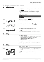
Page 17: ... reverts to the main display 5 2 Start up If the boiler was powered off 1 Check that the heating system and the boiler are adequately primed with water Recommended pressure 0 15 MPa 1 5 bar 2 Check that the storage tank is filled with fuel 3 Open the oil inlet valve 4 Switch on the boiler A venting cycle is run automatically The display shows the operating status of the boiler the heating flow tem...

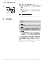
Page 18: ...a qualified profes sional if the home is left empty for a long period of time and there is a chance of frost Important To prevent the radiators and the installation from freezing in pla ces where that risk exists e g in a garage or an equipment room we recommend the connection of an outside temperature sensor to the boiler If the temperature of the water in the boiler falls too much the integrated...

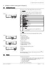
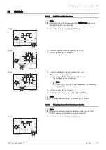
Page 19: ...menu access the next sub menu access the next parameter increase the value Press the key to access the previous menu access the previous sub menu access the previous parameter decrease the value Press the confirmation key to confirm a menu a sub menu a parameter a value When the temperature is displayed briefly pressing the back key h will return to the time display 6 2 Start up If the boiler was ...

Page 20: ...ing a PCB 1 Access the menus by pressing the two keys on the right simultane ously 2 Access the PCB selection menu only when several PCBs are present Important The PCB selection menu is available only when the icon flash es 3 Scroll through the names of the connected additional PCBs by pressing the or keys The names of the installed PCBs will be displayed in sequence 4 Confirm the required PCB by ...

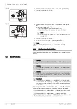
Page 21: ...s been shut down Note Press the key to restart the appliance the screen will display 5 Confirm by pressing the key 6 Go back to the main display by pressing the h key Note The display disappears after a few seconds of inactivity 6 3 2 Stopping domestic hot water production Note Domestic hot water production can be managed via the TIME PROG sub menu dedicated to timer programming 1 Go to stop mode ...

Page 22: ...ly protects the boiler not the heating system Caution Have the boiler and heating system drained by a qualified profes sional if the home is left empty for a long period of time and there is a chance of frost Important To prevent the radiators and the installation from freezing in pla ces where that risk exists e g in a garage or an equipment room we recommend the connection of an outside temperat...

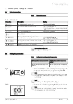
Page 23: ...etting the parameters 7 2 1 Setting the heating water temperature No temperature sensor connected Outside temperature sensor con nected Set the heating water temperature setpoint Set the required room temperature 1 Set the temperature setpoint or room temperature depending on the configuration described above by turning the setting button Note If the heating water temperature setpoint is lower tha...

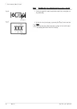
Page 24: ... turning the set ting button 2 Go back to the main display by pressing the key for two seconds Note After five seconds without pressing any keys on the control panel the display goes back to the main display Fig 36 MW 3000246 3 Fig 37 MW 3000245 3 7 Control panel settings B Control 24 EFU FF 7641178 v03 25072017 ...

Page 25: ...erature set point for the heated zone if no outside temperature sensor has been connected For the CU OH04 PCB Can be set from 7 to 90 C For the SCB 04B PCB Can be set from 7 to 100 C 75 C 50 C CP080 Activity zone 1 temperature set point Can be set from 5 to 30 C 16 C 16 C CP081 Activity zone 2 temperature set point Can be set from 5 to 30 C 20 C 20 C CP082 Activity zone 3 temperature set point Can...

Page 26: ...etting not available 10 C CP510 Circuit temporary room temperature set point Can be set from 5 to 30 C 20 C 20 C CP540 Temperature set point for SWIMMING POOL mode Can be set from 0 to 39 C not available 20 C CP550 Chimney zone off on 0 0 CP570 Do not modify this setting 0 0 CP660 Select the icon to display this zone on the room sensor none all bedroom living room office outside kitchen basement 3...

Page 27: ...ration off on 1 not available AP073 SUMMER WINTER set point switch Can be set from 15 to 30 C set to 30 5 C function deactivated 22 C only accessible to the installer AP074 SUMMER override off on 0 0 AP082 Applying summer winter time off on 1 not available For more information see Browsing in the menus page 19 Selecting a PCB page 20 8 1 2 COUNTERS TIME PROG CLOCK menus Tab 10 List of sub menus Su...

Page 28: ...f reversal valve cycles X DC003 Number of hours reversal valve operation hours X DC004 Number of burner start ups in domestic hot water production mode X DC005 Number of hours of burner operation in domestic hot water production mode hours X PC002 Number of burner start ups X PC003 Number of hours of burner operation hours X PC004 Number of safety lock downs E36 X AC002 Number of hours burner oper...

Page 29: ... the h key For more information see Browsing in the menus page 19 Selecting a PCB page 20 8 2 2 Setting the heating Caution Altering the factory settings may impair operation of the appliance Note The heating mode can be managed using the TIME PROG menu 1 Access the heating parameters by pressing the key 2 Select the desired circuit if there are several PCBs by pressing the or key 3 Confirm the se...

Page 30: ...ature set point by pressing the key Go back to the main display by pressing the h key 8 2 4 Setting the timer programming 1 Access the COUNTERS TIME PROG CLOCK menus Important The COUNTERS TIME PROG CLOCK menus are only accessible when the icon flashes Important When using a programmable room thermostat this menu is not displayed 2 Select the desired circuit by pressing the or key 3 Confirm the se...

Page 31: ...on by pressing the key 8 Select the status that correspond to the period by pressing the or keys Status to for periods to Description comfort mode reduced mode 9 Confirm the selection by pressing the key 10 Repeat steps 8 to 11 to define the comfort periods to and the associated status to Note No setting 10 minutes The setting determines the end 11 Go back to the main display by pressing the h key...

Page 32: ...e parameter available in the User menu 8 2 6 Reading out measured values The measured values are available in the Information menu of the dif ferent PCBs Certain parameters are displayed according to certain system configurations according to the options circuits or sensors actually connected Tab 13 List of sub menus Sub menu Description CU OH04 central unit PCB HMI control panel Tab 14 List of su...

Page 33: ...M060 Pump speed X CM120 Circuit operating mode AUTO manual frost protection temporary X X CM130 Current activity status frost protection reduced comfort anti legionella X X CM190 Desired room temperature set point C X X CM210 Temperature outside the zone X X DM001 Domestic hot water tank temperature C X X PM002 Heating temperature set point C X FXX XX Software version for the selected PCB X X PXX ...

Page 34: ...al set point limited internal set point normal output check temperature stabilisation time burner shutdown burner off closure of the shut off damper closure of the flue damper end of heat demand boiler shutdown boiler pump post operation time delay or domestic hot water back up start up time delay boiler pump or domestic hot water shutdown isolating valve closed start anti short cycle off awaiting...

Page 35: ... Check the hydraulic pressure in the installation Caution If the hydraulic pressure is lower than 0 08 MPa 0 8 bar more water should be added Top up the water level in the heating in stallation to reach a hydraulic pressure of between 0 15 and 0 2 MPa 1 5 and 2 0 bar 2 Carry out a visual check for any water leaks 9 2 2 Topping up the installation with water 1 Open the valves on all radiators conne...

Page 36: ...nting valve with the bleed key keeping a cloth pressed against the vent 8 Wait until water comes out of the venting valve and then close the venting valve Warning The central heating water may still be hot 9 Switch the boiler on A three minute venting cycle is performed automatically 10 After venting check that the water pressure in the installation is still adequate Important If the water pressur...

Page 37: ...e appliance s functions and thus eradicates the fault If several faults occur they are displayed one after the other 1 Reset the control panel by pressing the key for 3 seconds when an error message is displayed In economy mode the appliance will not run a domestic hot water heating cycle after a central heating cycle 2 Display the current operating status by briefly pressing the key 10 2 2 Access...

Page 38: ... key When this menu opens the row of the error in the log appears briefly The PCB name appears Go back to the error list by pressing the h key Note The errors are stored from the most recent to the oldest 6 Go back to the display by pressing the h key Press the key the parameter flashes after the errors cor responds to the PCB selected Clear the error log by pressing the key 7 Exit the Malfunction...

Page 39: ...o not hang curtains in front of the radiators Install reflective panels behind the radiators to prevent heat losses Insulate the pipes in rooms that are not heated cellars and lofts Close the radiators in rooms not in use Do not run hot or cold water pointlessly Install an energy saving shower head which can save up to 40 ener gy Take showers rather than baths A bath consumes twice as much water a...

Page 40: ...liable for material damage intangible los ses or physical injury resulting from an installation that does not comply with Legal or regulatory requirements or provisions laid down by the local au thorities National or local regulations and special provisions relating to the instal lation Our manuals and installation instructions in particular in terms of regular maintenance of the appliances Our wa...

Page 41: ...el LWA indoors dB 52 53 See For specific precautions on assembly installation and mainte nance see the chapter on Safety Instructions 13 2 Product fiche Temperature Controls Tab 18 Product fiche for the Temperature controls B Control Class III Contribution to space heating energy efficiency 1 5 13 3 Product data sheet Temperature controls Tab 19 Product data sheet for the Temperature controls IniC...

Page 42: ...acteristics Boiler and supplementary heat pump installed with low temperature heat emitters at 35 C Seasonal space heating energy efficiency class of package Seasonal space heating energy efficiency of package OR Seasonal space heating energy efficiency in Supplementary heat pump Tank rating Collector efficiency in Tank volume in m Collector size in m Seasonal space heating energy efficiency in Su...

Page 43: ...ed whereby Prated is related to the preferential space heater Tab 20 Weighting of boilers Psup Prated Psup 1 2 II package without hot water storage tank II package with hot water storage tank 0 0 0 0 1 0 3 0 37 0 2 0 55 0 70 0 3 0 75 0 85 0 4 0 85 0 94 0 5 0 95 0 98 0 6 0 98 1 00 0 7 1 00 1 00 1 The intermediate values are calculated by linear interpolation between the two adjacent values 2 Prated...

Page 44: ...13 Appendix 44 EFU FF 7641178 v03 25072017 ...

Page 45: ...13 Appendix 7641178 v03 25072017 EFU FF 45 ...

Page 46: ...13 Appendix 46 EFU FF 7641178 v03 25072017 ...

Page 47: ...hnological information contained in these technical instructions as well as any drawings and technical de scriptions supplied remain our property and shall not be multiplied without our prior consent in writing Subject to alterations ...

Page 48: ...51 D 48282 EMSDETTEN DE DIETRICH THERMIQUE Iberia S L U ES www dedietrich calefaccion es 34 935 4 75 850 info dedietrich calefaccion es C Salvador Espriu 11 08908 L HOSPITALET de LL OBREGAT CZ www dedietrich cz 420 271 001 627 dedietrich bdrthermea cz WALTER MEIER Klima Schweiz AG CH www waltermeier com 41 0 44 806 41 41 41 0 44 806 41 00 group waltermeier com Bahnstr asse 24 CH 8603 SCHWE RZENBAC...

Reviews: