background image

IGT-30 Series 

36 

12.  Remove the antennae cover from the panel. 


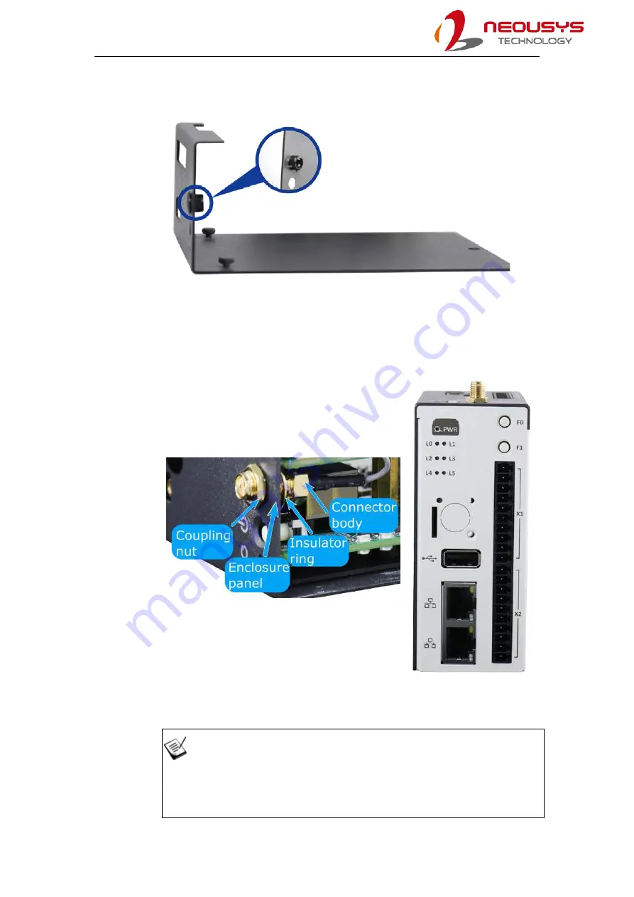
13.  To install the SMA female connector, make sure the coupling nut sits outside the 

enclosure panel, insulator ring sits inside the enclosure panel with the connector 

body. Fasten the SMA female connector by turning the coupling nut and the 

connector body in opposite directions. Reinstall the cover plate and panel. 


SMA female connector installation 

Reinstall cover and 

enclosure 


NOTE 

Please fasten the SMA female connector before installing the cover and 

enclosure! 

Summary of Contents for IGT-30 Series

Page 1: ...Neousys Technology Inc IGT 30 Series Industrial Gateway User Manual Revision 1 0...

Page 2: ...tem Status LED 16 3 2 Ethernet Port LED 17 4 Digital I O and DC Connector 4 1 Digital Input Connector X1 Pin Definition 18 4 2 Digital Output Connector X2 Pin Definition 19 4 3 Serial Port X3 Console...

Page 3: ...in advance with Neousys Technology Inc Customer is solely responsible for ensuring the compatibility and interoperability of the third party s products Customer is further solely responsible for ensur...

Page 4: ...o part 15 of the FCC Rules These limits are designed to provide reasonable protection against harmful interference when the equipment is operated in a commercial environment This equipment generates u...

Page 5: ...c Neousys Technology Inc shall not be liable for any direct indirect special incidental or consequential damages arising from the use of the product or documentation nor for any infringement on third...

Page 6: ...cords and other connection cables away from foot traffic Do not place items over power cords and make sure they do not rest against data cables Shutdown disconnect all cables from the system and grou...

Page 7: ...y as possible while assuring proper connector engagement ESD Precautions Handle add on module motherboard by their retention screws or the module s frame heat sink Avoid touching the PCB circuit board...

Page 8: ...T 30 series an industrial grade gateway that can be deployed in a complex communication network The manual covers IGT 30 series connections LED indicators initial setup and installation of the system...

Page 9: ...conditions IGT 30 series supports PoE Powered Device PD mode meaning it can be powered by a LAN cable from a PoE Power Sourcing Equipment PSE and at the same time transfer data via this cable as well...

Page 10: ...for mass production Inherited from its predecessor IGT 30 series features six LED indicators and two function buttons that can be programmed by users The function buttons can act as controls for IGT...

Page 11: ...ired RS 232 port User LED 6x user programmable LED Function button 2x user programmable function buttons Power button 1x power button Reset button 1x reset button CAN bus NA Isolated CAN bus port 2 0...

Page 12: ...r damaged please contact your local dealer or Neousys Technology 2 1 IGT 30 IGT 30D Packing List System Item IGT 30 IGT 30D Qty 1 IGT 30 or IGT 30D 1 2 3 pole terminal block 1 3 10 pole terminal block...

Page 13: ...sys IGT 30 enclosure dimensions come in a footprint measuring just 103 65 H x 43 0 W x 76 5 D mm The compact dimensions make it easy to setup and deploy in areas where space is limited It also comes w...

Page 14: ...is a power status indicator LED six user definable LEDs microSDHC expansion slot under cover plate SIM card slot USB port Ethernet port two user definable function buttons two DI DO connectors consol...

Page 15: ...IGT 30 Series 15 2 4 Enclosure Top View Top of the enclosure features a 3 pin DC power connector serial port RS 232 422 485 console port power button reset button and an antenna opening...

Page 16: ...description Preset status PWR Power Green System on Off System off Power status indicator with green color On if power on and off if power off L0 LED 0 Amber User definable Amber LED User defined beha...

Page 17: ...two ports that may be used for system s initialization The LED status indicator light functions are described as below LED indicator Color Status description Connection status Amber Steady on Connecti...

Page 18: ...el comprises of ten pins starting with Pin X1 1 from the top in numeric order downwards to X1 10 It is dedicated for digital input functions Pin Channel Description Pin Channel Description X1 1 DI_COM...

Page 19: ...dedicated for digital output functions Pin Channel Description Pin Channel Description X2 1 DO_0_A Digital output 0 X2 6 Reserved Reserved pin Please keep it unconnected X2 2 DO_0_B X2 7 X2 3 DO_1_A...

Page 20: ...and RS 485 The following table shows the definition of the ten pins Pin Channel RS 422 RS 485 RS 232 X3 1 TX TX of ttyS1 Data of ttyS1 Rx of ttyS1 X3 2 TX TX of ttyS1 Data of ttyS1 X3 3 RX RX of ttyS1...

Page 21: ...finition T he DC connector also locates at the top of the system Please take care of the polarity while wiring to DC input DC Connector Pin Pin Description V Positive polarity of DC input V Negative p...

Page 22: ...ng the process please observe all ESD procedures to avoid damaging the equipment For internal external microSDHC installation or replacement make sure the system has powered off Before disassembling y...

Page 23: ...r fingernail to push in the card and the card will spring out just enough for you to retract them out of the slot 3 The card insertion is directional So gently insert the card if you feel like the car...

Page 24: ...ase of the system The battery is user provided and is responsible for the system s real time clock To access the internal and microSDHC and battery slot you must remove the panel and cover To do so pl...

Page 25: ...30 Series 25 3 Place your thumbs firmly on the side of the panel gently push upwards to disengage and remove it 4 Once you have removed the cover unfasten two screws that secure the PCBA in the enclos...

Page 26: ...the battery on a 45 angle as shown below and press down indicated by the arrow on the other end to clip the battery in place Insert battery at 45 angle Battery clipped into place NOTE The BR2032 batt...

Page 27: ...icroSDHC card 8 Place the replacement microSDHC card in the slot make sure the notch matches indicated by the red circle flip the holder over to sit on top of the microSDHC car and slot push in the di...

Page 28: ...Gently slide the PCBA back into the enclosure making sure the connectors buttons meet the enclosure openings Slide back into enclosure Make sure connectors meet 10 Secure the two screws holding the PC...

Page 29: ...IGT 30 Series 29 11 Install the panel fasten the screws to secure the enclosure panel and cover plate Install the cover Secure enclosure cover Secure cover plate...

Page 30: ...CIe Mini Installation To access the PCIe Mini card you must disassemble the enclosure and cover To do so please perform the following procedure 1 Unfasten the screw on the panel 2 Unfasten the screw h...

Page 31: ...30 Series 31 3 Place your thumbs firmly on the side of the panel gently push upwards to disengage and remove it 4 Once you have removed the panel unfasten two screws that secure the PCBA in the enclos...

Page 32: ...IGT 30 Series 32 5 Gently pull the PCBA out of the enclosure 6 Insert the SIM card as shown below...

Page 33: ...IGT 30 Series 33 7 Locate the PCIe Mini slot and inset the module on a 45 degree angle 8 Gently press the module down and secure the module with the dedicated screw...

Page 34: ...e Mini module s antennae please refer to the module s user manual on antennae cable connection NOTE Please note how the antennae cable is routed This is the recommended routing path to accommodate SMA...

Page 35: ...nclosure making sure the connectors buttons meet the enclosure openings and the SMA female connector is accessible Make sure connectors meet Make sure SMA female connector is accessible 11 Secure the...

Page 36: ...nsulator ring sits inside the enclosure panel with the connector body Fasten the SMA female connector by turning the coupling nut and the connector body in opposite directions Reinstall the cover plat...

Page 37: ...IGT 30 Series 37 14 Secure the panel and cover plate by fastening respective screws Fastening the cover plate screw Fastening the cover screw 15 Install the antennae to complete the installation...

Page 38: ...s been initialized The Din rail has been proven to be most beneficial in the industrial environment where space is limited The mount plate comes with two M4 screws Please refer to the illustration bel...

Page 39: ...DIN rail tilting downwards overlap the top clip edge of the mount plate onto the DIN rail first then firmly press the bottom front of the enclosure to clip the bottom edge of the mount plate 3 Confirm...

Page 40: ...ure you have done the following 1 Connect and plug in the 3 pole terminal block WARNING Please make sure the voltage of DC power is correct before you connect it to the system Supplying a voltage over...

Page 41: ...minal application such as PuTTY 6 1 Login via Console Port Establish a connection between your host computer and IGT 30 s console port connector 1 pins CTX CRX and GND Please note that a cross over ca...

Page 42: ...T 30 Series 42 3 Go back to Category Session select and it should bring up the parameters set in the previous step Click on Open when ready 4 A series of messages may appear wait for igt30 login promp...

Page 43: ...r root to login password is not required and the Linux CLI prompt root igt30 will appear From here you may begin configuring your IGT 30 NOTE Please remember to change the default password root to avo...

Page 44: ...at the Ethernet port on IGT 30 supports AUTO MDIX meaning either a straight through or cross over cable can be used 1 On your host computer please go to Start Control Panel View network status and tas...

Page 45: ...IGT 30 Series 45 3 Enter the following IP parameters and OK IP Address 192 168 8 1 Subnet Mask 225 225 225 0...

Page 46: ...as the destination you want to connect to Click on Open when ready 5 A verification prompt may appear click on Yes to continue and the PuTTY command prompt will show login as enter neousys and press...

Page 47: ...IGT 30 Series 47 6 To acquire root rights type in sudo su and press Enter 7 The root prompt should appear...

Page 48: ...eleased button returns value 1 Get digital input DI0 7 status no voltage input return value 1 Set and get LED L0 5 status setting 1 to LED makes the light turn on Be care that preset LED function migh...

Page 49: ...hich is simply open or short but polarity do not matter Most mechanical switches such as limit switch and buttons fall into this category The built in digital input channels of IGT 30D and IGT 31D sup...

Page 50: ...signals The following figure shows how to wire the digital output devices to the digital input channels Sinking DO wiring Sourcing DO wiring When the dry contact mode switch of each digital input chan...

Page 51: ...s SPST NO stands for single pole single throw and normally open It works like dry contact mechanical relays Turning the digital output channels on will close the circuit polarity does not matter The d...

Page 52: ...0 brightness invert trigger L1 sys class leds igt30 usr1 L2 sys class leds igt30 usr2 L3 sys class leds igt30 usr3 L4 sys class leds igt30 usr4 L5 sys class leds igt30 usr5 Button F0 sys class gpio gp...

Reviews: