background image


133 

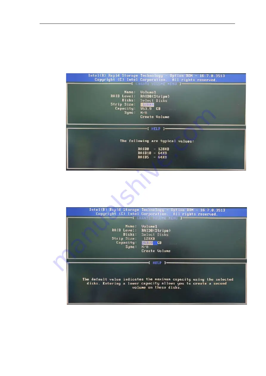
9.  For 

Stripe Size

, use the up and down arrow key to select between 4KB, 8KB, 16KB, 

32KB, 64KB, 128KB for your RAID volume stripe size and press ENTER to access the 

Capacity

 setting. 

*RAID1(Mirror) does not offer Stripe Size options. 


10. You may enter the RAID volume capacity you wish to create at this step and press the 

Enter key to complete your RAID settings. By default, the maximum capacity will be 

applied. Once you have entered a capacity, press ENTER to confirm. 


Summary of Contents for Nuvo-7000 Series

Page 1: ...Neousys Technology Inc Nuvo 7000 Series User Manual Revision 1 3...

Page 2: ...7000DE Bottom View 27 1 4 Nuvo 7000LP Dimension 28 1 4 1 Nuvo 7000LP Front Panel View 28 1 4 2 Nuvo 7000LP Rear Panel View 28 1 4 3 Nuvo 7000LP Top View 29 1 4 4 Nuvo 7000LP Bottom View 30 2 System Ov...

Page 3: ...Nuvo 7000E P DE Only 96 3 3 Installing the System Enclosure 100 3 4 Wall Mount Bracket DIN rail Installation 105 3 4 1 Wall Mount Bracket Installation 105 3 4 2 DIN rail Installation Optional 107 3 5...

Page 4: ...and Driver Installation 150 Appendix A Using WDT DIO WDT and DIO Library Installation 160 WDT Functions 162 InitWDT 162 SetWDT 162 StartWDT 163 ResetWDT 163 StopWDT 163 Appendix B PoE On Off Control...

Page 5: ...in advance with Neousys Technology Inc Customer is solely responsible for ensuring the compatibility and interoperability of the third party s products Customer is further solely responsible for ensur...

Page 6: ...part 15 of the FCC Rules These limits are designed to provide reasonable protection against harmful interference when the equipment is operated in a commercial environment This equipment generates us...

Page 7: ...ot represent commitment from Neousys Technology Inc Neousys Technology Inc shall not be liable for any direct indirect special incidental or consequential damages arising from the use of the product o...

Page 8: ...cords and other connection cables away from foot traffic Do not place items over power cords and make sure they do not rest against data cables Shutdown disconnect all cables from the system and grou...

Page 9: ...y as possible while assuring proper connector engagement ESD Precautions Handle add on module motherboard by their retention screws or the module s frame heat sink Avoid touching the PCB circuit board...

Page 10: ...Cassette and MezIOTM interface Nuvo 7006DE Intel Coffee Lake 8th 9th Gen Core i fanless embedded controller with 6x GbE 2 slot PCIe Cassette and MezIOTM interface Nuvo 7006E PoE Intel Coffee Lake 8th...

Page 11: ...ry Version Date Description 1 0 Mar 2019 Initial release 1 1 Apr 2019 Updated maximum 15mm 2 5 SSD HDD thickness supported 1 2 Jul 2019 Updated 9 th Gen Intel processor support 1 3 Dec 2020 Updated DI...

Page 12: ...lution for extra functionalities Users can install off the shelf PCIe and PCI add on card s into the expansion Cassette select MezIO TM module for extra functions such as DIO RS 232 422 485 GbE USB3 o...

Page 13: ...ernet port 2x Gigabit Ethernet ports by I219 and I210 Nuvo 7002E 6x Gigabit Ethernet ports by I219 and 5x I210 Nuvo 7006E PoE IEEE 802 3at PoE PSE for Port 3 Port 6 Nuvo 7006E PoE 100 W total power bu...

Page 14: ...TM expansion port for Neousys MezIO TM modules Power Supply DC Input 1x 3 pin pluggable terminal block for 8 35VDC DC input Remote Ctrl LED Output 1x 3 pin pluggable terminal block for remote control...

Page 15: ...15 For sub zero operating temperature a wide temperature HDD or Solid State Disk SSD is required...

Page 16: ...ts by I219 and 5x I210 Nuvo 7006P PoE IEEE 802 3at PoE PSE for Port 3 Port 6 Nuvo 7006P PoE 100 W total power budget USB via Intel native xHCI controller 4x USB 3 1 Gen2 10Gbps ports 4x USB 3 1 Gen1 5...

Page 17: ...MezIO TM modules Power Supply DC Input 1x 3 pin pluggable terminal block for 8 35VDC DC input Remote Ctrl LED Output 1x 3 pin pluggable terminal block for remote control and PWR LED output Maximum Pow...

Page 18: ...orts by I219 and 5x I210 Nuvo 7006DE PoE IEEE 802 3at PoE PSE for Port 3 Port 6 Nuvo 7006DE PoE 100 W total power budget USB via Intel native xHCI controller 4x USB 3 1 Gen2 10Gbps ports 4x USB 3 1 Ge...

Page 19: ...t for Neousys MezIO TM modules Power Supply DC Input 1x 3 pin pluggable terminal block for 8 35VDC DC input Remote Ctrl Status Output 1x 3 pin pluggable terminal block for remote control and PWR LED o...

Page 20: ...ports by I219 and 5x I210 Nuvo 7006LP PoE IEEE 802 3at PoE PSE for Port 3 Port 6 Nuvo 7006LP PoE 100 W total power budget USB via Intel native xHCI controller 4x USB 3 1 Gen2 10Gbps ports 4x USB 3 1 G...

Page 21: ...ansion port for Neousys MezIO TM modules Power Supply DC Input 1x 3 pin pluggable terminal block for 8 35VDC DC input Remote Ctrl LED Output 1x 3 pin pluggable terminal block for remote control and PW...

Page 22: ...Nuvo 7000E P Dimension NOTE All measurements are in millimeters mm Applicable to Nuvo 7002E 7006E 7006E PoE Nuvo 7002P 7006P 7006P PoE 1 2 1 Nuvo 7000E P Front Panel View 1 2 2 Nuvo 7000E P Rear Pane...

Page 23: ...23 1 2 3 Nuvo 7000E P Top View...

Page 24: ...24 1 2 4 Nuvo 7000E P Bottom View...

Page 25: ...n NOTE All measurements are in millimeters mm Applicable to Nuvo 7002DE 7006DE 7006DE PoE 1 3 1 Nuvo 7000DE Front Panel View 1 3 2 Nuvo 7000DE Rear Panel view The numbers 2 5 represents the height of...

Page 26: ...26 1 3 3 Nuvo 7000DE Top View...

Page 27: ...27 1 3 4 Nuvo 7000DE Bottom View...

Page 28: ...n NOTE All measurements are in millimeters mm Applicable to Nuvo 7002LP 7006LP 7006LP PoE 1 4 1 Nuvo 7000LP Front Panel View 1 4 2 Nuvo 7000LP Rear Panel View The numbers 2 5 represents the height of...

Page 29: ...29 1 4 3 Nuvo 7000LP Top View...

Page 30: ...30 1 4 4 Nuvo 7000LP Bottom View...

Page 31: ...items 1 2 Accessory box which contains CPU bracket Neousys drivers utilities DVD Wall mount bracket Foot pad 3 pin power terminal block HDD thermal pad for 2 5 HDD SSD if HDD is not installed Screw p...

Page 32: ...ou ordered CPU RAM HDD please verify these items 1 2 Accessory box which contains CPU bracket Neousys drivers utilities DVD Wall mount bracket Foot pad 3 pin power terminal block HDD thermal pad for 2...

Page 33: ...fferent Nuvo 7000E P DE Nuvo 7000LP No Item Description 1 USB3 1 Gen 2 port USB3 1 Gen 2 port SuperSpeed offers up to 10Gbps twice the bandwidth over existing SuperSpeed USB3 1 Gen 1 connection It is...

Page 34: ...Ethernet ports by I219 and 5x I210 Nuvo 7006E P DE 8 Reset button Use this button to manually reset the system 9 LED indicators From left to right the LEDs are IGN ignition control WDT watchdog timer...

Page 35: ...natively in Windows 10 therefore you do not need to install the xHCI driver prior to utilizing USB functions 2 2 2 USB3 1 Gen 1 Port The system s USB 3 0 Gen 1 ports 5Gbps are implemented via native x...

Page 36: ...adapter cable depending on the display device connected It supports resolutions up to 1920x1200 60Hz The system supports triple independent display outputs by connecting display devices to VGA DVI and...

Page 37: ...multiple display outputs and achieve best VGA output resolution in Windows you need to install corresponding graphics drivers Please refer to section OS Support and Driver Installation for details NOT...

Page 38: ...ort passive DP adapter cable You can connect to other display devices using DP to HDMI cable or DP to DVI cable DP to HDMI DP to DVI The system supports triple independent display outputs by connectin...

Page 39: ...d Micro SIM cards are secured into the sockets via push push type mechanisms The push push mechanism means the SIM card is push to install and push to retrieve Please note that the SIM1 micro SIM card...

Page 40: ...E PSE Power Sourcing Equipment compliant with IEEE 802 3at each PoE port delivers up to 25W to a Powered Device PD PoE can automatically detect and determine if the connected device requires power or...

Page 41: ...cess the reset button 2 2 9 LED Indicators There are four LED indicators on the I O panel IGN WDT HDD and PWR The descriptions of these four LED are listed in the following table Indicator Color Descr...

Page 42: ...erval between on off operations i e once the system is turned off there is a 5 second wait before you can power on the system 2 2 11 Hot swappable 2 5 HDD SSD Slot Nuvo 7000LP Series Only The Nuvo 700...

Page 43: ...s thermal conditions of both the system and the add on card The modular concept brought by Cassette module also reduces the complexity of installing and replacing an add on card in the fanless control...

Page 44: ...Cassette module can be accessed from this side of the panel No Item Description 1 MezIO TM I O Reserved for MezIO TM I O connector Connector may vary depending on your choice of MezIO TM 2 4 Pole 3 5m...

Page 45: ...ced inside a cabinet Area in green Cassette module The cassette module offers a separate compartment to manage thermal conditions and reduce installation complications of an add on card Area in red Re...

Page 46: ...n uses high definition audio Realtek ALC262 codec There is a female 4 pole audio jack for headphone speaker output and microphone input To utilize the audio function in Windows you need to install cor...

Page 47: ...e RS 232 422 485 ports COM3 and COM4 in blue are standard 9 wire RS 232 ports The operation mode of COM1 and COM2 can be set in BIOS setup utility The following table describes the pin definition of C...

Page 48: ...terminal block can also accept ignition signal input IGN when ignition control module eg MezIO V20 is installed for in vehicle applications WARNING Please make sure the voltage of DC power is correct...

Page 49: ...sely placed behind the panel To clear the CMOS please refer to the following procedure 1 Please power off and unplug the system and refer to the section Disassembling the System on how to remove the f...

Page 50: ...up to 64GB Each slot supports single module DDR4 2666MHz SODIMM up to 32GB capacity NOTE When changes are made to DRAM module s such as additionally install or remove and reinstall into the same diff...

Page 51: ...this socket and the system will automatically detect and configure it to run PCIe or SATA signals This mini PCIe socket is designed with SIM card slot indicated in red support With a SIM card install...

Page 52: ...5V 1 5V 29 GND GND 30 SMB_CLK SMB_CLK 31 PETn0 SATA_Txn 32 SMB_DATA SMB_DATA 33 PETp0 SATA_Txp 34 GND GND 35 GND GND 36 USB_D 37 GND GND 38 USB_D 39 3 3V 3 3V 40 GND GND 41 3 3V 3 3V 42 43 GND 44 45 R...

Page 53: ...card slot 1 is the default functioning slot The system has an M 2 2242 slot indicated in blue that works with dual SIM slots 4G 3G on the front panel indicated in red By installing a 3G or 4G M 2 modu...

Page 54: ...28 31 USB3 0 RX 30 UIM1 RESET 33 GND 32 UIM1 CLK 35 USB3 0 TX 34 UIM1 DATA 37 USB3 0 TX 36 UIM1 PWR 39 GND 38 41 PERn0 SATA B 40 UIM2 DET 43 PERp0 SATA B 42 UIM2 DATA 45 GND 44 UIM2 CLK 47 PETn0 SATA...

Page 55: ...blue features a 7 pin SATA connector and a 4 pin power connector The power connector indicated in red accommodates a 2 5 HDD SSD in internal HDD bracket Standard 22 pin SATA connectors are provided wi...

Page 56: ...to the OFF position when BIOS upgrade has completed The table below shows the system default DIP switch settings for reference purposes System Default DIP switch setting Enable BIOS upgrade Nuvo 7000...

Page 57: ...tandby mode 4 Standby Power 5 HDD Output Hard drive indicator flashing when SATA hard drive is active 6 HDD 7 Power Output System power indicator on if system is turned on off if system is turned off...

Page 58: ...58 2 4 8 Internal USB 2 0 Port The system s motherboard has an internal USB2 0 port on the PCBA You can utilize this USB port to connect a USB protection dongle inside the chassis of the system...

Page 59: ...or an Intel Optane TM memory to accelerate the read write performances of traditional hard disk drive An NVMe SSD offers exceptional performance over 2 5 SSDs while Intel Optane TM memory can dramatic...

Page 60: ...3 17 PERN2 18 3V3 19 PERP2 20 21 GND 22 23 PETN2 24 25 PETP2 26 27 GND 28 29 PERN1 30 31 PERP1 32 33 GND 34 35 PETN1 36 37 PETP1 38 39 GND 40 41 PERn0 SATA B 42 43 PERp0 SATA B 44 45 GND 46 47 PETn0 S...

Page 61: ...s also mechanically reliable benefited from its 3 point mounted mezzanine structure A MezIO TM module can leverage these signals to implement comprehensive I O functions The system incorporates MezIO...

Page 62: ...round Reserved UID_LED 17 18 PCIE_TXP_1 PCIe data pair Platform reset PLT_RST 19 20 PCIE_TXN_1 PCIe data pair USB data pair USBP5_N 21 22 PCIE_RXP_1 PCIe data pair USB data pair USBP5_P 23 24 PCIE_RXN...

Page 63: ...vice this product to avoid injury or damage to the system Please observe all ESD procedures at all times to avoid damaging the equipment Before disassembling your system please make sure the system ha...

Page 64: ...tem enclosure you need to remove the Cassette module and screws on both I O panels 1 Turn the system upside down and remove the four screws at the bottom of the Cassette module NOTE Not applicable to...

Page 65: ...65 3 On the front I O panel remove the hexa screws indicated below Nuvo 7000E P DE systems Nuvo 7000LP systems...

Page 66: ...66 4 Remove the front I O panel Nuvo 7000E P DE systems Nuvo 7000LP systems...

Page 67: ...67 5 On the rear I O panel remove the hexa screws indicated below Nuvo 7000E P DE systems Nuvo 7000LP systems...

Page 68: ...68 6 Remove the rear I O panel Nuvo 7000E P DE systems Nuvo 7000LP systems...

Page 69: ...ft the system s bottom panel Nuvo 7000E P DE systems Nuvo 7000LP systems NOTE For Nuvo 7000LP systems please disengage the 22 pin SATA cable connected to the 2 5 hot swappable tray before removing the...

Page 70: ...70 8 Once the bottom panel has been removed you should have access to the system s internal I O interfaces...

Page 71: ...ent is significantly different 3 2 1 CPU Installation Procedure 1 To install the CPU you will need to separate the heatsink and the motherboard 2 To do so remove the nine screws indicated below if you...

Page 72: ...ou ll see the CPU socket protective cover place finger tips underneath the sign REMOVE for leverage and gently lift the cover WARNING With the protective cover removed please be careful when handling...

Page 73: ...ainer tray Match the two notches on the side to the protrusions in the socket gently lower the CPU into the socket 5 Locate the CPU retention bracket from the accessory box Place the retention bracket...

Page 74: ...herboard around and secure the bracket by tightening two M3 P head screws Hold CPU bracket firmly and turn the motherboard around Secure two M3 P head screws 7 Remove all thermal pads protective films...

Page 75: ...75 8 With the four motherboard standoffs aligned gently lower the motherboard onto the heatsink and secure the four screws...

Page 76: ...sure to the CPU chipset die You ll want to apply even pressure to the corners by gradually tightening each screw Please refer to the recommended order when tightening the screws 10 Reinstall the syste...

Page 77: ...DR4 2666 Please follow the procedures below to replace or install the memory modules 1 Please refer to the section Disassembling the System 2 Locate the SODIMM memory module slots on the motherboard 3...

Page 78: ...y module down until it is clipped in 5 Repeat steps 3 and 4 to install the other module 6 Reinstall the system enclosure and panel when done 7 If you need to install other components please refer to r...

Page 79: ...ng instructions 1 Please refer to the section Disassembling the System 2 Locate the mPCIe and SIM card slots on the motherboard 3 Before installing the mPCIe module you need to insert the Mini SIM car...

Page 80: ...gle Secure the module 6 Clip on the IPEZ to SMA cable to the module and secure the antenna to the front or rear panel Please refer to the module s manual for clip on connection Clip on IPEZ to SMA cab...

Page 81: ...d 1 slot is the default functioning slot The system has an M 2 slot indicated in blue for installing 3G 4G or a WiFi module that can be coupled with dual Micro SIM card slots indicated in red For inst...

Page 82: ...with the gold fingers facing downward If you are inserting the SIM card with the system upright heatsink fins upwards the gold fingers should be facing upward The SIM socket utilizes push push mechan...

Page 83: ...f traditional hard disk drive An NVMe SSD offers exceptional performance over 2 5 SSDs while Intel Optane TM memory can dramatically boost your traditional hard disk drives read write performances For...

Page 84: ...screw 4 Reinstall the system enclosure and panel when done 5 If you need to install other components please refer to respective sections 6 Please refer to the section Intel Optane TM Memory BIOS Setup...

Page 85: ...ucture A MezIO TM module can leverage these signals to implement comprehensive I O functions The system incorporates MezIO TM interface and universal mechanical design to accommodate Neousys standard...

Page 86: ...86 2 The MezIO TM module is secured by the three stand mounts indicated in the illustration below...

Page 87: ...to the three stand mounts while matching the MezIO TM interface Secure the module using three screws supplied 4 Reinstall the system enclosure and panel when done 5 If you need to install other compon...

Page 88: ...in power connectors indicated in red The SATA and power cables should already be connected on the motherboard so users only need to install the HDD SSD Please refer to the following instructions on ho...

Page 89: ...ring the HDD SSD thermal pad 3 Place the HDD SSD with labels facing up and match the SATA connector end to the side with two screw holes indicated in blue secure the HDD SSD with the supplied flathead...

Page 90: ...into the system with the connector side being inserted into the system first and secure the tray with three screws Reinsert the tray Securing the tray 6 If you need to install other components please...

Page 91: ...tors indicated in red The SATA and power cables should already be connected on the motherboard so users only need to install the HDD SSD A 2 5 SATA HDD SSD can be installed to the internal tray or the...

Page 92: ...lace the thermal pad in the middle and remove the protective film covering the thermal pad 4 Place the HDD SSD onto the tray with the label side facing upward and the SATA connector facing the side wi...

Page 93: ...93 5 Insert the connector end first of the installed HDD SSD and tray into the system 6 Secure using the three screws that were removed earlier...

Page 94: ...ase refer to the following procedure 1 Pull the handle on the 2 5 external hot swappable slot to open it Pull handle Open slot door 2 With the label side facing upward insert the SATA connector side o...

Page 95: ...the cable connection 1 To install and make use to the panel screw fix connection you must acquire panel screw fix cables such as the cable shown below 2 Simply insert the RJ45 connector into the RJ45...

Page 96: ...tmentalizes the heat generated and effectively manages thermal conditions of both the system and add on card s The modular design reduces the complexity of installing and replacing add on card s in th...

Page 97: ...97 2 Gently wiggle the Cassette module and separate it from the system enclosure 3 Remove the screw to open the Cassette cover...

Page 98: ...bezel is properly inserted into the notch and the card is secured in place with screw Remove bezel cover Make sure the card is inserted into the notch and secured with a screw Nuvo 7000DE systems hav...

Page 99: ...99 5 Secure the screw indicated in the blue circle 6 Gently lower the Cassette module back onto the system enclosure and secure the module onto the system enclosure by securing the following screws...

Page 100: ...lling the System Enclosure 1 To reinstall the system enclosure place the bottom panel on top of the motherboard while making sure both sides are inserted into the heatsink indicated in blue Nuvo 7000E...

Page 101: ...101 Nuvo 7000LP systems NOTE For Nuvo 7000LP systems please connect the 22 pin SATA cable connected to the 2 5 hot swappable tray before installing the bottom panel...

Page 102: ...102 2 Install the front panel and secure screws indicated in blue Nuvo 7000E P DE systems Nuvo 7000LP systems...

Page 103: ...103 3 Install the rear panel and secure screws indicated in blue Nuvo 7000E P DE systems Nuvo 7000LP systems...

Page 104: ...104 4 Install the Cassette module and secure screws indicated in blue NOTE Not applicable to Nuvo 7000LP systems...

Page 105: ...if they have been attached 3 4 1 Wall Mount Bracket Installation To install the system as a wall mount device please refer to the following instructions 1 Take out the two wall mount brackets and fou...

Page 106: ...106 3 when wall mounting place the heatsink fins perpendicular to the ground for better heat dissipation efficiency...

Page 107: ...and a DIN rail mounting clip By fixing the clip to the bracket using four M4 flat head screws and fixing the bracket assembly to the system four M4 screws complete the installation by clipping the sys...

Page 108: ...your system The power button on the front panel is a non latched switch and behaves as the ATX mode on off control With DC power connected pushing the power button will turn on the system and the PWR...

Page 109: ...l To setup and power on off the system using an external non latched switch ATX mode please follow the steps described below 1 Acquire a non latched switch with 3 pin plug 2 Connect the non latched sw...

Page 110: ...on To enable WOL function please set up WOL settings in the BIOS and in the operating system by follow the steps described below 1 When the system boots up press F2 to enter BIOS setup utility 2 Go to...

Page 111: ...AC Address is 78h D0h 04h 0Ah 0Bh 0Ch DESTINATION SOURCE MISC FF FFFFFFFFFF 78 D0 04 0A 0B 0C 78 D0 04 0A 0B 0C 78 D0 04 0A 0B 0C 78 D0 04 0A 0B 0C 78 D0 04 0A 0B 0C 78 D0 04 0A 0B 0C 78 D0 04 0A 0B 0...

Page 112: ...Please always make sure you understand the effect of change before you proceed with any modification If you are unsure of the function you are changing it is recommended to change one setting at a tim...

Page 113: ...ssion you may set the Slew Rate option as High to improve signal quality For RS 422 485 communication the RS 422 485 Termination option determines whether to enable disable internal termination of RS...

Page 114: ...ng instructions on how to enable the high speed mode for your COM port COM1 used as an example To set COM port high speed mode 1 Press F2 when the system boots up to enter the BIOS setup utility 2 Go...

Page 115: ...compatibility issue s with some PCIe add on cards To set PEG delay in milliseconds 1 When system boots up press F2 to enter BIOS setup utility 2 Go to Advanced System Agent SA Configuration PEG Port C...

Page 116: ...e SATA hard drive read write speeds by installing an Optane memory into the M 2 slot Please refer to the section Intel RST Premium With Intel Optane System Acceleration for details Recommended SATA co...

Page 117: ...A mSATA or M 2 port you wish to set and press ENTER to bring up setting options Scroll to and highlight the setting you wish to set and press ENTER 4 Repeat step 3 to set other SATA ports 5 Press F10...

Page 118: ...signed with on board TPM 2 0 module As TPM 2 0 requires 64 bit Windows 10 with UEFI boot mode it is enabled in BIOS by default To enable TMP availability 1 When system boots up press F2 to enter BIOS...

Page 119: ...cription Auto Wake on S5 Disabled The system does not turn on when operating in state S5 By Every Day The system turns on each day when operating in state S5 Specify the time of day By Day of Month Th...

Page 120: ...wer Off System is kept in off state when DC power is supplied To set Power On after Power Failure option 1 When system boots up press F2 to enter BIOS setup utility 2 Go to Power Power On after Power...

Page 121: ...erformance with CPUs of 35W TDP you can install a 65W CPU and limit its SKU power to 35W to obtain more computing power This feature gives you the flexibility of CPU selection and great balance betwee...

Page 122: ...ave to enable this option first in BIOS settings Please refer Powering On Using Wake on LAN to set up the system To enable disable Wake on LAN option 1 When system boots up press F2 to enter BIOS setu...

Page 123: ...ia listed are approved as boot media Legacy Boot Type Only legacy boot media listed are approved as boot media UEFI Boot Type Only UEFI boot media listed are approved as boot media Quick Boot Enabled...

Page 124: ...e operating system to control system power management USB Boot Enabled Allow boot from bootable USB devices Disabled Does not allow boot from bootable USB devices EFI Device First Enabled Set to boot...

Page 125: ...artition for disk and VBIOS for video initialization the UEFI boot mode uses GPT partition which supports greater than 2TB partition size and GOP driver for faster video initialization NOTE If you cho...

Page 126: ...irst device to boot or the last in the boot sequence To set the newly installed boot device as the first or last boot device 1 Press F2 when the system boots up to enter the BIOS setup utility 2 Go to...

Page 127: ...OS is selected the user must stop the watchdog timer once booted into the OS This guarantees the system can always boot into the OS otherwise another booting process will be initiated For information...

Page 128: ...1 When system boots up press F2 to enter BIOS setup utility 2 Go to Boot UEFI 3 Highlight the device you wish to make boot order changes to and press F5 F6 or to change device boot order To select bo...

Page 129: ...r to using the AMT function to remotely control the system you need to configure AMT password and network settings 1 Connect Ethernet cable toI219 LM Ethernet port indicated in blue 2 When the system...

Page 130: ...data before you create or modify RAID volume s as the process may cause irreversible data deletion When creating a RAID volume it is also recommended to use hard drives from the same batch same brand...

Page 131: ...ess ENTER to set boot type 4 Press F10 to Exit Saving Changes and reboot the system 5 When the system reboots press Ctrl I to enter the RAID configuration utility 6 Once you re in the Configuration Ut...

Page 132: ...u wish to create Enter a name and press ENTER to access the RAID Level setting 8 For RAID Level use the up and down arrow key to select between RAID0 Stripe or RAID1 Mirror settings Select a RAID mode...

Page 133: ...e and press ENTER to access the Capacity setting RAID1 Mirror does not offer Stripe Size options 10 You may enter the RAID volume capacity you wish to create at this step and press the Enter key to co...

Page 134: ...need to press ESC and start again from Step 5 If all settings are correct and you wish to continue with Create Volume highlighted press ENTER to begin creating the RAID volume 12 A data deletion warn...

Page 135: ...n utility will bring you back to the main screen showing the RAID volume and their member disks 14 The above process was to create a RAID 0 volume If you wish to create a RAID 1 volume please perform...

Page 136: ...nable RAID functionality in UEFI mode 1 When system boots up press F2 to enter BIOS setup utility 2 Go to Advanced SATA And RST Configuration SATA Mode Selection highlight Intel RST Premium With Intel...

Page 137: ...ENTER to set boot type 4 Press F10 to Exit Saving Changes and reboot the system 5 When the system reboots press F3 to enter the Configuration Utility 6 Once you re in the Configuration Utility highli...

Page 138: ...138 7 The following screen shows Non RAID physical disks and the option Create RAID Volume Highlight Create RAID Volume and press ENTER to begin creating your RAID volume...

Page 139: ...139 8 The Name option allows you to name your RAID volume Press ENTER when ready to go to the next option...

Page 140: ...140 9 The RAID Level option allows you to select RAID 0 stripping or RAID 1 mirror for your RAID volume Press ENTER when ready...

Page 141: ...disk drives for your RAID volume Highlight a drive and press ENTER use up down arrow keys to highlight x and press ENTER to confirm the selection A minimum of two disk drives must be selected for RAI...

Page 142: ...onfigure the stripe size of your RAID volume Available stripe sizes are 4KB 8KB 16KB 32KB 64KB 128KB use the up and down arrow keys to highlight and press ENTER to confirm the stripe size selection RA...

Page 143: ...3 12 The Capacity MB option allows you to configure the storage capacity of your RAID volume By default the full storage capacity will be applied Once you have entered a capacity press ENTER to confir...

Page 144: ...144 13 The Create Volume option is the final step in the volume creation process Highlight Create Volume and press ENTER to begin creating your RAID volume base on the settings you just configured...

Page 145: ...is successfully created 15 Press F10 to save and Esc to exit the Intel Rapid Storage Technology configuration page NOTE The above process was to create a RAID 0 volume If you wish to create a RAID 1 v...

Page 146: ...ally compile and install the driver for Intel graphics or I210 GbE controller if the driver is not embedded in kernel You can visit Intel website for further information For distributions graphics dri...

Page 147: ...ystem and installs all necessary drivers for you system with a single click To install drivers automatically please refer to the following procedures 1 Insert the Drivers Utilities DVD into a USB DVD...

Page 148: ...indows 10 x64 The recommended driver installation sequence is 1 Chipset driver x Driver_Pool Chipset_CFL Win_10_64 SetupChipset exe 2 Graphics driver x Driver_Pool Graphics_CFL_SKL_APL Win_10_64 igxpi...

Page 149: ...in prior to use these functions Please note that you must install WDT_DIO_Setup_v2 2 9 x or later versions Windows 10 x64 Please execute the driver setup program in the following directory x Driver_Po...

Page 150: ...eaturing a dual media disk combination ultrafast media for file and block caching slow media for storage capacity that is presented to the host OS as a single SSD The ultra fast media utilizes PCIe NV...

Page 151: ...151 3 Go to SATA Mode Selection press ENTER to bring up options select Intel RST Premium With Intel Optane System Acceleration and press ENTER to select the option...

Page 152: ...trolled and press ENTER to select the option 5 Press F10 to save and exit and allow the system to boot into Windows 6 In Windows download Intel RST driver if you don t already have it on hand Right cl...

Page 153: ...153 7 Follow the 6 step setup procedure as instructed...

Page 154: ...154 8 Check the I accept the terms in the License Agreement box and click on Next to continue the installation process...

Page 155: ...155 9 When done click on Finish and restart the system...

Page 156: ...n will appear Click on Next to continue 11 In the Setup section you will see your Intel Optane memory drive and compatible drive s that can be accelerated Click on the downward arrow to bring up a sel...

Page 157: ...ntel Optane memory module before proceeding Check the box Erase all data on Intel Optane memory module and click on Continue 13 When the Intel Optane memory module has been enabled the installation wi...

Page 158: ...em restart a successful enablement message will appear to indicate the Intel Optane memory module has been enable successfully 15 Once enabled the RST software Setup section should show your configura...

Page 159: ...Windows 10 x64 and WOW64 platform For other OS support please contact Neousys Technology for further information Installing WDT_DIO Library The WDT_DIO function library is delivered in the form of a s...

Page 160: ...To setup WDT DIO Library please follow instructions below 1 Execute WDT_DIO_Setup 2 2 9 x exe and the following dialog appears 2 Click Next and specify the directory of installing related files The de...

Page 161: ...o reboot the system The WDT DIO library will take effect after the system has rebooted 4 When programming your WDT or DIO program the related files are located in Header File Include Library File Lib...

Page 162: ...RD tick BYTE unit Description Set timeout value and unit for watchdog timer When InitWDT is invoked a default timeout value of 255 seconds is assigned Parameter tick WORD value 1 65535 to indicate tim...

Page 163: ...returns TRUE otherwise FALSE Usage BOOL bRet StartWDT ResetWDT Syntax BOOL ResetWDT void Description Reset the timeout value to the value given by SetWDT If ResetWDT or StopWDT is not invoked before W...

Page 164: ...programming PoE on off control function NOTE Nuvo 7000E P series will be shown in illustrations for demonstration purposes GetStatusPoEPort Syntax BYTE GetStatusPoEPort Byte port Description Get curre...

Page 165: ...signated PoE port Parameter port BYTE value specifies the index of PoE port Please refer to the following illustration port should be a value of 1 4 Return Value TRUE if enabled success FALSE if fail...

Page 166: ...ignated PoE port Parameter port BYTE value specifies the index of PoE port Please refer to the following illustration port should be a value of 1 4 Return Value TRUE if disabled success FALSE if fail...

Reviews: