9
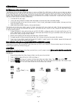
4.4. Installation of the pH / ORP sensors (only in NEO-XX PH and NEO-XX +).
1.
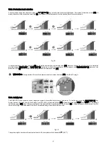
Insert the pH / ORP sensors into their corresponding places of the holder (Fig. 12)
2.
To that purpose, loosen the connection screws and insert the sensor into the holder.
3.
The sensors must be installed in the holder so that it is guaranteed that the sensors located in their ends are always submerged in the
water circulating through the pipe.
4.
Always install the pH / ORP sensors vertically or with a maximum inclination of 40
o
(Fig. 13).
Fig. 12
Fig. 13
4.5. Control inputs of the power supply (Look on the board power supply)
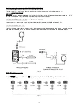
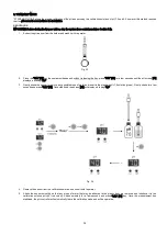
Besides basic operations, the NEO Series electrolysis system has three inputs for voltage-free contacts, enabling the connection of additional
external controls. They are located on connector [CN7] of the power card (Fig. 17).
Fig. 17
The logic associated to these three inputs can be programmed during the system configuration process
[FS]
OPTIONAL EXTERNAL FLOW DETECTOR CONTROL (not included with the equipment): input for potential-free contact. When the
contact connected to this input is open (external flow detector at rest), and the [FS] is configured as [FS1c], the electrolysis system switches off
due to the flow alarm. Connect the external flow detector wiring to the respective input [FS], placed in the [CN7] connector, on the unit’s power
card.
Fig. 18
Summary of Contents for NEO-12
Page 2: ......
Page 5: ...3 3 DATASHEET...
Page 6: ...4...
Page 7: ...5 Fig 1...
Page 9: ...7 4 3 Electrical connections...
Page 10: ...8...
Page 14: ...12 4 7 Connection PoolStation...
Page 18: ...16 Fig 23 System programming flow sheet...
Page 29: ...27 7 1 3 REPLACEMENT AND CLEANING THE LAMP U V...
Page 30: ...28...
Page 31: ...29...


