________________________________________________________________________________________
Document No. DOC-IPC-003,
User Manual iPC-Series & nPC300, Rev C Rel. 11-2014
Page 18 of 27
3
2
1
3
1 2
TOP VIEW
FRONT VIEW
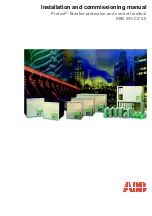
PHOENIX CONTACT P.N. 1777992
Connecting Power to the iPC-Series
Connecting power to the Panel Mount, Rack Mount, and nPC300 units:
The iPC-Series and nPC300 units are powered from 100-240 VAC, 50/60 Hz or optionally from 24
VDC.
Damage will occur if 100-240 VAC power is connected to an
i
PC-Series unit equipped with the 24
VDC input power option.
iPC-Series equipped units with the 24 VDC
option will have a “-DC” suffix in their
model number (such as
i
PC1500T-i5-4GB-80SS-W7-DC)
Because the iPC-Series (not
–EN option) is UL 1604 listed for Hazardous Location use, (Class I
Division2, Groups A, B, C, D; Class II Division 2 Groups F and G: Temperature Code T6 or T4A), the units do
not have a power switch for switching off supplied power. Consideration should be give to the installation of an
appropriately rated external power switch if the application requires powering off the iPC-Series unit.
Power is connected to the units through a removable Phoenix Contact plug (Phoenix Contact P.N.
1777992) that allows for screw termination of field wiring. This plug is included with each unit and is keyed to
prevent installation in a unit with the wrong input voltage rating.
When Field Wiring to these terminals the
use of 18 AWG or greater (12 AWG maximum) copper wire with 60ºC or 60/75ºC wire insulation and the
terminal tightening torque of 7.0 lb/in. (0.79 Nm) is required.
The terminal screws are shown in
“Top View”
below. Connect the field wiring according to the appropriate voltage in the table below. Strip the wire insulation
back on each conductor
6.5 mm (0.26 in)
and assure that the remaining wire is twisted together, not frayed,
and clean. If an outer jacket over each conductor is utilized then strip the outer jacket back an additional
19.0
mm (0.75 in)
as shown in figure below. When installing the conductors take care that there are not any stray
strands of wire that can contact an adjoining connection. Tinning of each lead can be utilized to prevent frays if
desired. Optionally the included protective cover can be utilized to prevent electrical shocks when handling the
power connector and provide strain relief for each conductor connection (see the following section for
installation instructions). After the connections are made, make sure the plug retention screws (the two screws
shown in the “Front View” below) are securely tightened. This will prevent the plug from pulling out. The use of
these screws is mandatory when the unit is utilized in applications requiring hazardous locations approvals.
FRONT VIEW
PIN NUMBER
100 VAC
– 240 VAC INPUT
18 VDC
– 36 VDC INPUT
1
AC Line Input
+ DC Input
2
AC Neutral Return
-
DC Return
3
Protective Earth Ground
Protective Earth Ground
3
1 2