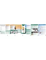
background image


NWC


611


10


Key


to


three

phase


electrical


system


diagram


NTCB


Boiler


temperature


probe


EVA


Aquastop


solenoid


valve


NTCV


Tank


temperature


probe


EVR


Regeneration


solenoid


valve


SDET


Detergent


sensor


EVS


Brine


discharge


solenoid


valve


SBRIL


Rinse


aid


sensor


PB


Rinse


aid


peristaltic


pump


SFIL


Filter


sensor


PD


Detergent


peristaltic


pump


FLMT


Flowmeter


EVF


Filler


solenoid


valve


SS


Salt


sensor


PS


Drain


pump


RD


Door


sensor


PLB


Boiler


pressure


switch


PR


Rinsing


pump


PLV


Tank


level


pressure


switch


PL


Washing


pump


PSV


Tank


safety


pressure


switch


PLB


Boiler


level


pressure


switch


AQS


Aquastop


microswitch


THB


Boiler


safety


thermostat


SB


Motherboard


M


Terminal


board


SI


Interface


board


LF


RFI


filter


TM


Terminal


board


ground


FUSE


Mains


fuse


TV


Tank


ground


CB


Boiler


contactor


TF


RFI


filter


ground


RB


Boiler


heating


element


TPL


Washing


pump


ground


T

FU


Overtemperature


fuse


TPR


Rinsing


pump


ground


THRV


Tank


safety


thermostat


TRV


Tank


heating


element


ground


RV


Tank


heating


element


TB


Boiler


heating


element


ground


Warning


!!!


The


warewasher


is


always


powered


up


unless


the


master


switch


is


turned


off.


Connect


the


appliance


to


the


user’s


earth


system.


The


terminal


for


the


connection


is


in


the


bottom


right

hand


corner


of


the


appliance.


The


earth


wire


(PE)


is


yellow

green


in


colour,


the


neutral


wire


(N)


is


blue


and


the


live


wires


(L1,


L2,


L3)


are


black,


grey


and


brown.


THE


POWER


SUPPLY


CABLE


MUST


BE


REPLACED


BY


THE


MANUFACTURER


OR


AN


AUTHORISED


SERVICE


CENTRE


TO


PREVENT


ALL


RISKS.


Summary of Contents for NWC 611

Page 1: ...PROFESSIONAL DISHWASHER...

Page 2: ...ds 14 5 6 Adjusting detergent and rinse aid dispensing 15 1 MALFUNCTIONS SHOWN ON THE DISPLAY FOR THE TECHNICIAN 16 2 INSTRUCTIONS FOR THE USER 17 2 1 Control panel 17 2 2 Before washing 17 2 3 First...

Page 3: ...r the proper use of your warewasher TECHNICAL INSTRUCTIONS These are intended for the qualified staff who are to install commission and test the appliance and carry out any servicing and repairs INSTR...

Page 4: ...MAKING SURE THAT THIS PRODUCT IS DISPOSED OF CORRECTLY THE USER HELPS TO PREVENT POTENTIAL DETRIMENTAL EFFECTS ON HEALTH AND THE ENVIRONMENT WHEN DECOMMISSIONING THE APPLIANCE COMPLY WITH THE LOCAL W...

Page 5: ...F THE WAREWASHER MIGHT CAUSE IT TO TIP OVER PUTTING PEOPLE IN DANGER NEVER LEAVE THE WAREWASHER DOOR OPEN SINCE PEOPLE MIGHT TRIP OVER IT DO NOT DRINK ANY WATER LEFT IN THE DISHES OR WAREWASHER AT THE...

Page 6: ...re kPa bar 100 600 1 6 Water intake temperature C 15 C 60 C Max intake water hardness f 15 f Rinse cycle water consumption l 3 2 Boiler capacity l 8 Tank capacity l 22 Standard cycle duration with int...

Page 7: ...NWC 611 7 APPLIANCE DIMENSIONS AND CONNECTIONS KEY TO LETTERS USED IN DIAGRAM C SOLENOID VALVE Q EARTH TERMINAL E ELECTRICITY SUPPLY CABLE P PERISTALTIC HOSES S DRAIN HOSE...

Page 8: ...be disposed of in accordance with the relevant regulations When the product is decommissioned it must not be dumped in the environment it must be disposed of in accordance with the relevant regulation...

Page 9: ...sher is fitted with a drain pump and can operate with drain connections on the floor or wall Refer to the connection diagram for the maximum permitted height of wall drains see TECHNICAL DATA Caution...

Page 10: ...Motherboard M Terminal board SI Interface board LF RFI filter TM Terminal board ground FUSE Mains fuse TV Tank ground CB Boiler contactor TF RFI filter ground RB Boiler heating element TPL Washing pu...

Page 11: ...NWC 611 11 Figure 1 Appliance three phase electrical system diagram...

Page 12: ...rs onto their ends as shown If the detergent dispenser is not factory fitted it can be retrofitted after ordering the relative kit As an alternative an external dispenser can be fitted making the elec...

Page 13: ...he probe but due to the thermal inertia of the probe or its seat wait about 1 minute after the heating element power absorption reading to obtain the real temperature 5 3 Parameter programming procedu...

Page 14: ...er temperature offset 00 Real measured Offset M P7 Tank temperature offset 04 Real measured Offset M P8 Real temperature display 01 0 filtered 1 real F P9 Tank probe type 01 Do not modify Note for P6...

Page 15: ...e and increased by turning clockwise RB Rinse aid dispensing regulator screw Adjustments are made using the adjuster screw AS SHOWN The quantity dispensed is reduced by turning clockwise and increased...

Page 16: ...phon blocked the tank is empty due to siphoning when the drain pump is not running E 4 Boiler overheating Reduce boiler temperature to 80 Circuit board relay failed check circuit board and inspect boi...

Page 17: ...Replace circuit board 2 INSTRUCTIONS FOR THE USER 2 1 Control panel On off button Total emptying button tank and boiler L1 power on LED L2 pump out in progress LED Short cycle key Medium cycle key Lon...

Page 18: ...the pack 1 Turn on the mains water tap user CHECK 5 Switch on the master switch user the word OFF appears on the display 2 The level of detergent and rinse aid in the containers 4 That the filters are...

Page 19: ...er two go out The cycle starts after the hood has been raised and lowered While washing is in progress the display shows the water temperature in the tank During rinsing it shows the boiler temperatur...

Page 20: ...e once the program has started If the master switch is not turned off the appliance sets on the last cycle performed To change it press the key of the program required the light comes on To perform th...

Page 21: ...th automatic switch off Press the pump out button for about 2 the LED flashes and the pump out and automatic tank cleaning phase starts When pump out is complete the appliance switches to OFF status o...

Page 22: ...ar when not in use Clean surfaces thoroughly and often with a damp cloth use neutral non abrasive detergents which do not use chlorine compounds which corrode and damage stainless steel Do not use the...

Page 23: ...hy periods out of use If the warewasher is to be out of use for a fairly long period of time the detergent and rinse aid dispenser devices must be emptied to prevent crystallisation and damage to the...

Page 24: ...vice Plates glasses badly arranged Arrange plates glasses correctly Low washing temperature Check temperature shown on the display call the after sales service if less than 50 C Inappropriate cycle se...

Page 25: ...POSSIBLE CAUSE POSSIBLE REMEDY DISHES NOT PROPERLY DRIED Low rinsing temperature due to thermostop OFF and or water intake temperature below 50 Switch thermostop ON If the problem persists call the a...

Page 26: ...warewasher off and wait a few minutes then switch back on and perform another cycle if the problem persists call the after sales service E 5 Tank overheating Switch the warewasher off and wait a few...

Page 27: ...you with guidance about keeping your appliance functioning correctly and put you in touch with your nearest authorised Service Centre 020 8993 6198 Our whole product offering can be viewed at www nels...

Reviews: