Nedap MACE SMART Installation Manual Download Page 36

MACE SMART


Installation sheet


MOUNTING INSTRUCTIONS 

Please follow the next steps to properly mount the MACE Smart reader to a surface. 


1.


Position the reader 

Make sure that the reader is positioned such that it is placed correctly covering the cable 
entry hole and that the screw hole is located at the bottom side of the reader. 
 

2.


Mount the wall-plate on the required location  

The reader can be mounted to any surface, including directly to metal. The size of the 
holes that should be drilled depends on the material of your surface. Fix the wall-plate into 
its position using the two mounting screws attached and a torx T10 screwdriver.  
 

Surface material 

Size of holes 

Use of plugs 

Concrete or stone 

5.0 mm (0.20 inch) 

Yes 

Wood 

2.5 mm (0.10 inch) 

No 

 
3.


Feed the cable through the cable entry hole and connect the cable 

Connect the cable to the connector blocks attached according to the overview below. 
 

Nedap antenna interface  K1-6 


K2-1  RS485 A (-) 

Beeper_IN*  K1-5 


K2-2  RS485 B (+) 

Led_UL_IN*  K1-4 


K2-3  Ground 

Led_NA_IN*  K1-3 


K2-4  Data-1 / Data 

Ground  K1-2 


K2-5  Data-0 / Clock 

Power supply 12 - 24VDC  K1-1 


K2-6  Tamper switch (normally closed) 


K2-7  Tamper switch (common) 


4.


Place the connectors 

Place the connectors over the pin headers at the backside of 
the reader. Make sure that the correct connector block is placed  
on the correct pin header (6P vs. 7P). Place the connectors such  
that the topside of the connectors (recognizable by the screws)  
remains visible after it has been placed on the reader. 
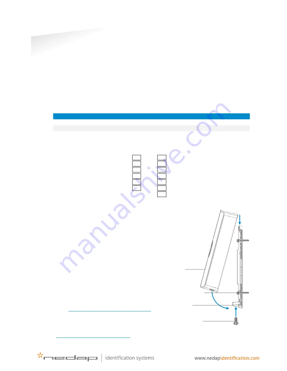
 

5.


Attach the MACE Smart reader onto the wall-plate 

Attach the reader onto the wall-plate according to  
the three steps in the illustration. Finish with fixing 
the assembly using the assembly screw at the  
bottom and the torx T10 screwdriver. 


INSTALL GUIDE 

More information about the configuration and 
installation of the MACE Smart reader can be found 
in the MACE Smart Install Guide, available on our  
partner portal 

https://portal.nedapidentification.com

.


TECHNICAL SUPPORT 

For technical support, please call: +31 (0)544 471 222 
or email 

[email protected]

Reader 

Wall-plate 

Mounting screws 

Assembly screw 

Summary of Contents for MACE SMART

Page 1: ...MACE Smart installation guide 2018 01 30 v1 03 5286484...

Page 2: ...___________________________________ 14 4 2 3 READ CONFIG ___________________________________________ 14 4 2 4 SETUP BAUDRATE ________________________________________ 14 4 2 5 SETUP OSDP DEVICE ADDRESS...

Page 3: ...ACE installation and order virtual MACE credentials that will be read by the MACE readers you plan to install 1 2 FIRMWARE VERSIONS The MACE Smart reader supports different firmware versions Below an...

Page 4: ...es MACE is NOT hot swappable so when making or changing connections power must be switched OFF The cable shield shall be connected with safety ground and the metal case of the external device s To be...

Page 5: ...able entry hole Properly fix the base plate into its position using the 2 screws When mounting on a stone or concrete wall drill 5mm holes for the plugs When mounting on wood drill with 2 5mm Install...

Page 6: ...NICATION 3 2 1 RS485 The MACE Smart reader has a RS485 interface for communication with a host system or to configure the reader settings RS485 is a 2 wire half duplex serial communication interface u...

Page 7: ...generate a Wiegand message If the credential is not programmed in Wiegand format you may configure the message output format as described in chapter 4 5 2 Make sure to order the correct credential pro...

Page 8: ...ribed in chapter 4 5 2 Make sure to order the correct credential programming format if you want to use the Wiegand or Magstripe interface See also the MACE how to order guide HTOG for more information...

Page 9: ...e controlled remotely by a connected access control system by activating digital inputs active low See chapter 3 for connection details Use MaceConfigTool software to setup the LED buzzer control mode...

Page 10: ...NA_IN active low BLUE Input 2 Beeper_IN active low BLACK Ground SHIELD Shield connected to DC ground STANDARD firmware The digital inputs can be used to control the LED and buzzer See chapter 3 3 OSDP...

Page 11: ...ed to activate an external relay Mind flyback diode Use the OSDP_OUT command to control the output state The outputs allow for direct activation and deactivation plus timed operation OSDP output contr...

Page 12: ...7 Tamper switch common Contact ratings Max current 50 mA 0 5 Volt voltage drop Max switching voltage 24 VDC The tamper contact status is reported through OSDP_LSTATR event messages 3 7 NEDAP ANTENNA...

Page 13: ...e for future reference or when requesting technical assistance from Nedap or its business partners 4 1 CONFIG SOFTWARE The MaceConfigTool software allows to configure all settings for the MACE reader...

Page 14: ...es that the configuration was read successfully Security keys and passwords cannot be read from the reader 4 2 4 SETUP BAUDRATE Select the serial communication baud rate Possible selections are 1200 2...

Page 15: ...customer code is correct to make the reader ignore tags that have an invalid customer code You may change the customer code s in the reader You can configure up to 20 customer codes in the MACE reade...

Page 16: ...trol the LED and buzzer using the digital inputs The corresponding LED colors can be configured See chapter 3 3 Direct using serial commands The connected access control panel may control the LED and...

Page 17: ...ing and configuration of your application Advanced user mode settings Reader function Select the reader function This function is reserved for future use It might trigger the MACE app to require user...

Page 18: ...checking Set the TX correction to a positive value when the received signal is higher than expected In other words increasing the TX correction will result in a shorter range Note that smartphone spe...

Page 19: ...equired Enable Enable the MACE NFC reading Nedap user mode settings Application ID file number data length and offset For MACE the following settings are required Application ID A0000007151001 File nu...

Page 20: ...File number File number within range from 0 to 255 Communication mode Select Plain MACed or Enciphered Data length and offset Select the data length and offset in nibbles Set data length and offset b...

Page 21: ...s normally A0A1A2A3A4A5 MAD key for Mifare Plus is normally A0A1A2A3A4A5A6A7 A0A1A2A3A4A5A6A7 Block number Block number to read data from The block number must be in range from 0 to 3 For sectors 32 t...

Page 22: ...MACE Card Enable reading MACE Card HID iCLASS UID only Enable reading HID iCLASS UID The HID iCLASS UID is the read only 8 byte unique ID ISO15693 Enable reading ISO15693 Different RFID cards comply w...

Page 23: ...005 Can be any string of max 10 characters Add ID source If enabled the ID source will be sent as a 2 digit code that identifies how the ID number was read The ID source values can be changed See chap...

Page 24: ...64 on BLE 40050108B03BF925E6F04D34 CR LF 4005 prefix 01 id source BLE 08 id type UID64 B03BF925E6F04D34 id number OSDP example MACE UID64 on BLE 01 08 B0 3B F9 25 E6 F0 4D 34 01 id source BLE 08 id ty...

Page 25: ...suffix P2 Parity Enable add parity bits to add a leading and trailing parity bit to the Wiegand message The leading parity bit P1 is even calculated on the first half of the data bits The trailing pa...

Page 26: ...ion is only possible if ID number before conversion is max 80 bits When the ID number is not in decimal the result may be unexpected Suffix Constant suffix value Max 65 535 16 bits Wiegand configurati...

Page 27: ...ut will generate 16 preamble clock cycles before the message and 16 postamble clock cycles afterwards Prefix Constant prefix value transmitted before the ID number Max 16 digits ID number Select to ou...

Page 28: ...l generate a Magstripe message The ID number uses the 6 least significant hex digits right aligned and they are converted to 8 decimal digits MACE UID64 B03BF925E6F04D34 ID number 0xF04D34 15 748 404...

Page 29: ...and baud rate setting This might have been changed due to different firmware 4 6 2 KEY UPDATE The key update function updates the masterkey in the MACE Smart reader The MACE authentication keys for BL...

Page 30: ...ACE Card Operating temperature 30 60 C 22 140 F Power 12 24 VDC from power limited UL294 or UL603 Listed power source Current consumption 0 2A 12VDC 0 1A 24VDC Input 2 TTL digital inputs for LED contr...

Page 31: ...MACE SMART INSTALLATION GUIDE Part Numbers 31 34 B PART NUMBERS Readers Part number Description 9565914 MACE Smart...

Page 32: ...ransmitter Cet quipement est conforme a RSS 102 limites nonc es pour un environnement non contr l Cet quipement doit tre install et utilis avec une distance minimale de 3 mm entre le radiateur et votr...

Page 33: ...completeness its publication conveys no license under any patent or other right nor does the publisher assume liability for any consequence of its use specifications and availability of goods mentione...

Page 34: ...EVISION Version Date Comment 1 03 2018 01 30 Updated technical specification and product photos 1 02 2017 12 20 Updated technical specification and tamper contact status report OSDP 1 01 2017 10 02 Ad...

Page 35: ...add anything to the MACE Smart reader other than mentioned in this installation guide or indicated by NEDAP N V CONFIGURATION The MACE Smart reader can be configured easily using the MaceConfigTool so...

Page 36: ..._IN K1 5 K2 2 RS485 B Led_UL_IN K1 4 K2 3 Ground Led_NA_IN K1 3 K2 4 Data 1 Data Ground K1 2 K2 5 Data 0 Clock Power supply 12 24VDC K1 1 K2 6 Tamper switch normally closed K2 7 Tamper switch common 4...

Reviews: