background image

XN120  2OPBOX 


               XN120 2OPBOX Guide 

5- Test the 2OPBOX 


When the 2OPBOX is installed 
it will provide 2 slots. 

The slot numbers depend on which XN120 cabinet that the 2OPBOX 
is connected to. 
The 2OPBOX connected to the main cabinet will provide slots 5 & 6 
The 2OPBOX connected to expansion cabinet 1 will provide slots 11 & 
12 
The 2OPBOX connected to expansion cabinet 2 will provide slots 17 & 
18 
 
The slots used by the cards within the 2OPBOX can be confirmed by 
Program 10-03-01. 
Refer to the instructions supplied with either the BRIU or VOIPU card 
for details of the settings within Program 10-03-01. 
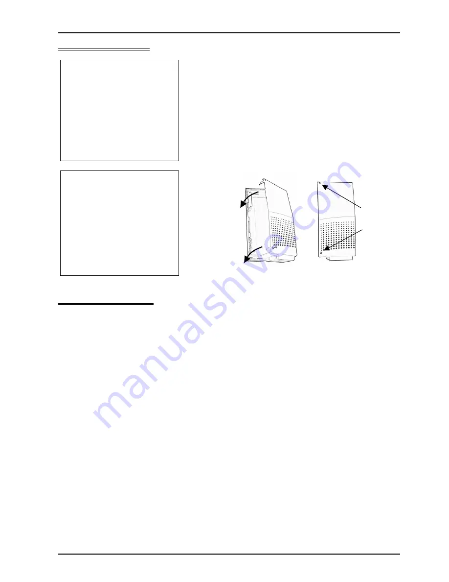


Replace the lid of the 
2OPBOX. 


Configure the XN120 

 
There is no configuration related to the 2OPBOX, the cards within it require configuration. Refer to the 
instructions supplied with either the BRIU or VOIPU card. 

Secure 
the two 
screws.

Locate the lid 
onto the right 
side edge of 
the 2OPBOX 
and lower into 
place. 
 

Summary of Contents for XN120 2OPBOX

Page 1: ...n supplied for future reference Regulatory Notice Refer to the Getting Started Guide 991409 5 supplied with the XN120 Main Unit for the Declaration of Conformity related to the product Warning This is a class A product In a domestic environment this product may cause radio interference in which case the user may be required to take adequate measures XN120 2OPBOX Guide Rev 1 1 February 2005 991419 ...

Page 2: ...20 2OPBOX Guide What is the 2OPBOX 3 Installation Procedure 3 1 Unpack the 2OPBOX 3 2 Fitting the 2OPBOX 4 3 Install the Option Cards 6 4 Connect the Power System Start Up 7 5 Test the 2OPBOX 8 Configure the XN120 8 ...

Page 3: ... ISDN cards or Voice over IP resource cards Installation Procedure 1 Unpack the 2OPBOX 2 Fit the 20OPBOX 3 Install the BRI VoIP cards into the 2OPBOX 4 Power on the XN120 5 Test the 2OPBOX 1 Unpack the 2OPBOX The 2OPBOX is supplied with 6 screws to fix the unit to the XN120 main expansion cabinet Additional Items Required Cross head screwdriver Small cutters pliers Optional Items The 2OPBOX can ha...

Page 4: ...t require fixing to the wall it is fixed directly to the XN120 unit 2 Remove the lid of the 2OPBOX 3 Power off the XN120 You must also power off any XN120 expansion units if they are installed 4 Using a pair of small cutters or pliers carefully remove the 3 breakouts on the right side of the XN120 base unit You will need to remove the lid of the XN120 first Remove the 3 breakouts on the right side...

Page 5: ...2OPBOX into the connector on the right side of the XN120 cabinet 6 Secure the 2OPBOX using the screws supplied There are two screws with self tapping thread and four with a machined thread 2OPBOX XN120 2 self tapping screws 4 machine screws 2OPBOX ...

Page 6: ...urther details The card can be installed into either slot of the 2OPBOX If you are only installing one option card it is recommended for logical port configuration that you fit the card into the slot marked CN1 2 Secure the card to the ETH plate at the front edge of the 2OPBOX Fit the option card into the guides and push firmly onto the connector Secure to the ETH plate ...

Page 7: ...ystem check that the NORMAL switch is set to ON This will ensure that the system memory retains your configuration The NORMAL switch is located to the right of the MOH Page connector on the main unit refer to the Getting Started Guide supplied with the XN120 for further information 2 The BRI VOIP card s will be automatically configured Refer to the instructions supplied with the option card for co...

Page 8: ...on cabinet 2 will provide slots 17 18 The slots used by the cards within the 2OPBOX can be confirmed by Program 10 03 01 Refer to the instructions supplied with either the BRIU or VOIPU card for details of the settings within Program 10 03 01 2 Replace the lid of the 2OPBOX Configure the XN120 There is no configuration related to the 2OPBOX the cards within it require configuration Refer to the in...

Reviews: