System Configuration and Setup 2-3
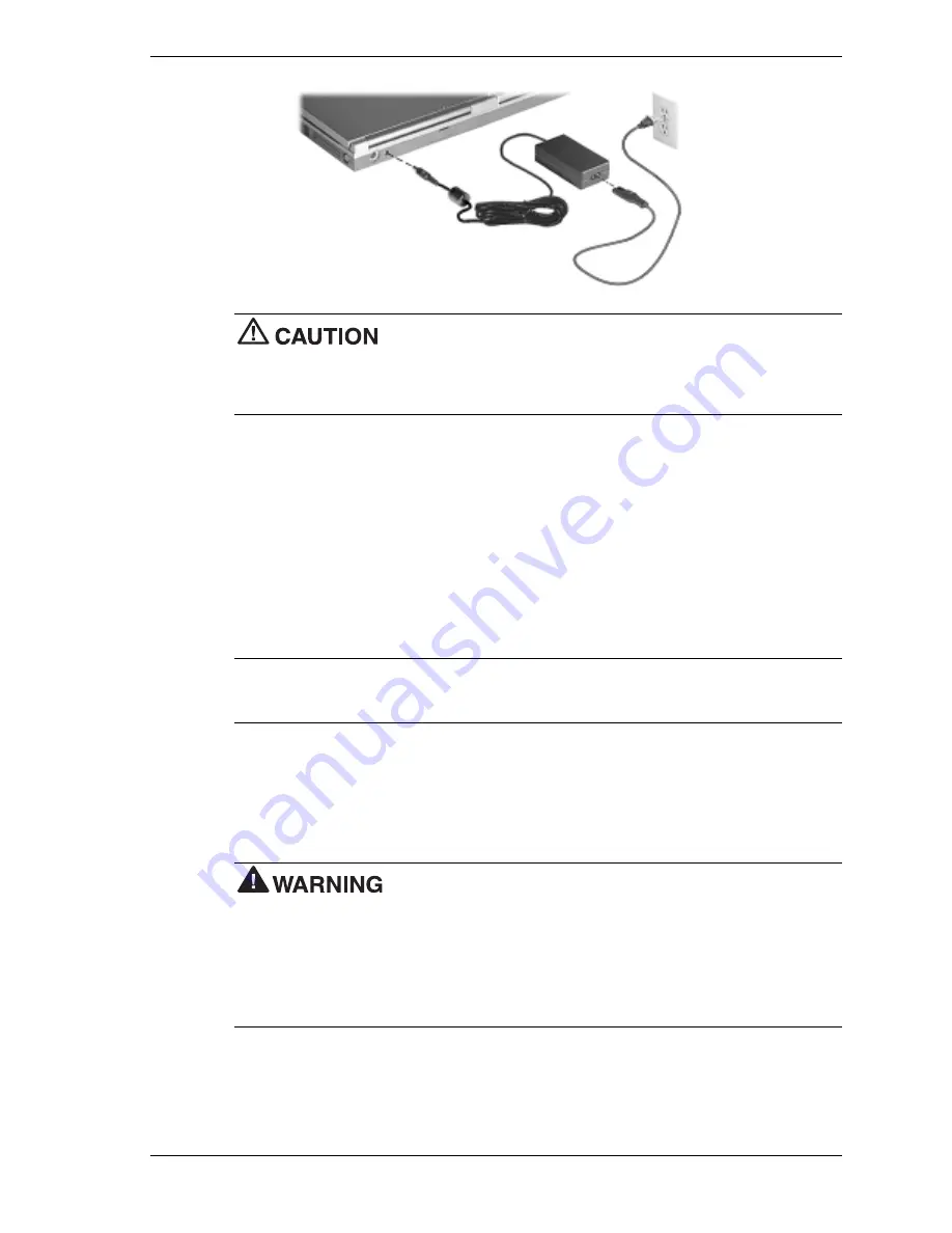
Do not cover or place objects on the AC adapter. Keeping the adapter
clear of objects lets the adapter cool properly during use.
Only use the AC adapter that comes with your NEC Versa VX. Although other adapters look
similar, using them can damage your system.
Powering the System On and Off
To power on, locate the Power button on the right hand side of the control panel above the
keyboard and press it.
To power off the system, press the Power button. In Windows, the
computer automatically shuts down, when “Shut Down” is selected from the Start menu. That is,
you do not need to press the Power button to switch off the computer.
Using the Battery
The NEC Versa VX system comes with a rechargeable Nickel Metal-Hydride (NiMH) or
Lithium-Ion (Li-Ion) battery. Battery packs are easy to install and remove.
Note
Although the battery is fully charged at the factory, transit and shelf time may reduce
the initial battery charge. We recommend that the first time you use your system, connect it to AC
power using the AC adapter. This also recharges your battery.
When battery power drops to the level where the Battery Warning is activated, the power LED
lights yellow.
When battery power reaches 8%, the power LED lights amber and the system beeps a warning
and the system goes into Suspend/Save to File mode.
To prevent accidental battery ignition or explosion, adhere to the
following:
!
Keep the battery away from extreme heat.
!
Keep metal objects away from the battery terminals to prevent a short circuit.
!
Make sure the battery is properly installed in the battery bay.
!
Read the precautions printed on the battery.
Summary of Contents for VERSA VX
Page 1: ...NEC Versa Notebook Computer NEC VERSA VX S E R V I C E A N D R E F E R E N C E M A N U A L...
Page 43: ...3 Disassembly and Reassembly Required Tools and Equipment Disassembly Reassembly...
Page 67: ...4 System Board Layout Audio Board DC DC Board I O Board Main Board...
Page 70: ...5 Illustrated Parts Breakdown Illustrated Parts Breakdown Parts List...
Page 71: ...5 2 Illustrated Parts Breakdown Illustrated Parts Breakdown...
Page 77: ...7 Troubleshooting Quick Troubleshooting Helpful Questions...
Page 87: ...9 Specifications System Components Connector Locations Memory Map Interrupt Controllers...


