


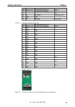


3.2.2 SW2, SW3
SW2 and SW3 are push switches. They are connected to pull-up resistors, and
their outputs go “Low”, when they are pushed.
Table 3-10 Switch SW2 and SW3 terminal list
Switch Signal name
Terminal CPU name at connection destination
SW2
P50
P50/TIQ01/TOQ01/RTP00/KR0
SW3
P51
P51/TIQ02/TOQ02/RTP01/KR1
Figure 3-4 Switches SW2 and SW3
3.2.3 SW4
SW4 is the reset switch. The TK-850/SG2+UZ board is reset when SW4 is pushed.
Figure 3-5 Switch SW4
3.2.4 LED5
The `Power LED’ LED5 is activated when the power supply is turned on.
Figure 3-6 LED5 as Power LED
3.2.5 LED1, LED2, LED3 and LED4
LED1, 2, 3 and 4 are available for applications. To turn on a LED, set the output
port to “Low”.
Table 3-11 LED 1, 2, 3 and 4 terminal list
LED
Signal name
Terminal CPU name at connection destination
LED1
PDH0
PDH0
LED2
PDH1
PDH1
LED3
PDH3
PDH3
Chapter 3
Hardware specification
24
User's Manual U19026EE3V0UM00


